Continue to Site

Eng-Tips is the largest engineering community on the Internet

Intelligent Work Forums for Engineering Professionals

  • Congratulations KootK on being selected by the Eng-Tips community for having the most helpful posts in the forums last week. Way to Go!

Electric motor NVH

Status
Not open for further replies.

onatirec

Mechanical
Aug 7, 2020
91
In gathering data to characterize noise and vibration in electric motors, I'm having trouble understanding some spectrogram features. The sharp vertical lines seem to behave very similar to pwm harmonics (see pic). They are flanked by sloped lines at multiples of twice the fundamental mechanical speed (f+-n*2*fm). This particular motor is an 18 slot / 12 pole PMSM, being driven up to 55Hz. The plot was made from acoustic pressure; the lines are apparent in accelerometer data as well.

The PWM switching frequency is 16kHz.

These lines are quite sharp and occur across the full operating range of the motor at multiples of ~4kHz.

Could these be pwm related?

Any other ideas as to what would produce these vibrations? An artifact of the DAS?
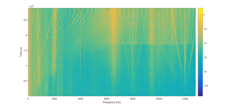
new_xvtwk0.png
 
Replies continue below

Recommended for you

I agree with Greg. Getting a spectrogram of the PWM waveform (or at least a spectrum at a given speed) for comparison seems like a good place to start.


=====================================
(2B)+(2B)' ?
 
18 slot / 12 pole PMSM
I'm trying to make sense of that.
You couldn't wind that for three phase in the way I'm used to seeing for traditional induction / synchronous motors.
Are there three phases supplied to the motor, or some other number of phases?

=====================================
(2B)+(2B)' ?
 
The inverter used was "integrated" into the motor, i.e. sealed up, making it very difficult to get a scope onto the pwm signal. I spun it up with another inverter we have in-house here. The lines were present even when changing around the pwm frequency to different values. So I'm thinking there's something else flipping in the inverter(s) at around 4kHz which is throwing up harmonics..

I believe there's an antialiasing filter built in to the DAS. Data were sampled at 25600, so I think it's unlikely aliasing would produce n*4k lines anyways.

E/m isn't exactly my specialty, so I'm not sure what you mean by the motor configuration. It's three phase AC, 18/12, concentrated windings. They are designed and built here.
 
I suspect it is because of the shape of the PWM Link. As the speed increases, the pulse length increases, thus reducing the period. I'm guessing the harmonics in general are caused by the square waves Link.

Perhaps try creating a fake PWM signal and do an FFT on it?
 
Status
Not open for further replies.

Part and Inventory Search

Sponsor