Continue to Site

Eng-Tips is the largest engineering community on the Internet

Intelligent Work Forums for Engineering Professionals

  • Congratulations IDS on being selected by the Eng-Tips community for having the most helpful posts in the forums last week. Way to Go!

Electrical Braking of a Linear Motor 1

Status
Not open for further replies.

GreenGiant117

Electrical
Oct 5, 2016
5
Hey all, new to the forum and I have a question.

I have an application where I have Linear motors moving quite a large mass, and to make the system at least a little safe I need to implement some braking. The difficult part of this is that the largest electrical brakes that I can find are only capable of stopping far less mass than I am dealing with, let alone the amount of space that I do not have to install them into.

Rather than pipe air out there and somehow find the space on the moving axes for the pneumatic brakes my thought was to implement electronic braking through shorting the windings.

I know there is a way to figure out how long it will take to slow the system down but I for the life of me cannot figure out how to plot this.

The information that I have so far is:
[ul]
[li]Mass: 200kg[/li]
[li]Back emf: 50 V/m/s [/li]
[li]Resistance per coil: 0.5 Ohm [/li]
[li]Newtons per amp: 46.5 [/li]
[/ul]

I know how to calculate instantaneous force generated, but I want a formula that can show me the curve of speed vs time, as well as current vs time and one for force vs time.

Thanks in advance,
Green
 
Replies continue below

Recommended for you

First off, how fast does it accelerate to the speed you use from a dead stop, and how does that compare you your desired stopping time? Because one truism is that you cannot stop it electrically any faster than it can start. So if it takes 3 seconds to accelerate and you want it to stop in 2 seconds, don't waste your time with electrical braking, friction is your only hope.


"You measure the size of the accomplishment by the obstacles you had to overcome to reach your goals" -- Booker T. Washington
 
The drive for the motors in question are undersized for the application, so for instance we can accelerate at a max of 2.5-3m/s/s but that is because we have limited current and voltage through the motor amplifier, the motor itself has a theoretical max acceleration of that mass is something like 7m/s/s with the right amplifier.

But it would not decelerate at that speed constantly, it would be a curve, since the faster it is going the more stopping force it will have,and vice versa, I just cannot figure out how to calculate that curve to see what the speeds would look like at certain times.
 
I wasn't referring to the rate, I was referring to the time. If your driver must go into current limit to accelerate, you will have the same problem trying to go the other way.

Also if you have a purely induction linear motor and an inverter driving it, no, you cannot just "short the outputs" to brake it. If it is a PM linear motor, you may be able to.


"You measure the size of the accomplishment by the obstacles you had to overcome to reach your goals" -- Booker T. Washington
 
As you increase the frequency of the inverter to accelerate, decrease the frequency of the inverter to decelerate.
You will have to add a braking resistor to the inverter or use a regenerating inverter.
If you don't have a VFD type inverter, consider one, or reverse the connections and plug it to a stop. You may have to add additional current limiting to the plugging circuit.
If you need emergency stopping you may be better off with air brakes, or spring applied, air released brakes.

Bill
--------------------
"Why not the best?"
Jimmy Carter
 
Drop Copper bars (or Aluminum) bars into the Magnet Rails. Very effective eddy current braking.
 
So I will isolate the motor from the drive, and essentially use resistors to load it and come to a stop.

I am not looking for a different solution to the problem here, I am going to use this method as least in test, then possibly move to large braking resistors if things get too hot.

The question I am asking is how to plot the speed change over time in the theoretical space before I actually build and test it out, that is all I am asking.

I have proven this method (shorting the windings of a linear motor to slow/stop it) in the small scale (2kg mass at 0.5m/s) but before I try it out on a larger scale test bed I want some graphs showing me how much braking I will actually achieve.
 
HOHOHO, Jolly Green Giant,

You have been asked a few times but never answered if this linear motor is PM or induction: both are available, although PM is most common.

So, to your specific question:

1) If it is an induction linear motor, no coil shorting will have any significant effect.
2) If it is PM, then yep, of course it will work.

You want the equation. It is very simple. I use it weekly to calculate stopping time on motors...

T=jw/t

where T is Torque
j is inertia
w is speed change
t is time

I use T in #-ft
so j in #-ft-sec^2
w is rad/sec so just use RPM speed change divided by 9.55
t is seconds.

So you have J of your motor; you gotta add the inertia of your load to this value to the total j

w is the speed you want to stop from of course.

Since you will be using back emf to generate the T, the T will decrease linearly with speed, so time to stop will be 2x the value calculated.

T is the torque you will apply to stop in time t.

Since you want to talk LINEAR instead of rotary motion, change the equation a tad to:

F=ma, and substitute in v=a*t so F=mv/t

So assuming you apply stopping force F the whole time t, you will stop mass m from speed v and all is well.
Again, since you will be using Bemf to generate F, F will decrease linearly with speed, so stopping time will be 2x what the max high speed F first applied is.

Applying YOUR values, you have 50v/(m/s)into .5 ohm coil. So assume you want to stop from 1m/sec: you will initially generate 50v... into .5ohms means you will have 100 amps flow. Since your motor Ft is 46.5n/a, you will generate 4,650n of initial stopping force... Avg is 1/2 that, so use 2,325n for F and t will come out correct.

So 2325n=m*(1m/s)/t or time to stop is m/2325 sec

assuming your motor mass is way less than your 200kg load mass, stop time is 200/2325 or in round numbers (I am not going to get out calculator - you can) about 100 msec.

Keep in mind that your motor may NOT be able to produce 4,650N of force - you must limit the current to the peak current the motor can safely work with (ie., keep peak force below the motor peak rating). If that is the case, you need to add R in series with the shorted windings to limit the current to safe value. If you do, of course your stopping force is reduced accordingly.

If you have significant FRiCTION force helping to stop it, you add that to the F in the equation for a total F available.

There you have it. You asked for an equation, it is above.


You asked also about heating of the resistors and sizing of wattage? You know the peak power dissipated is the max voltage and max current flow you allow; the avg heating on the resistors during the stop is exactly 1/2 that wattage since volts goes down linear.

I rounded the stop time to 2x the times to stop from peak; that is rounding and normally works fine in the real world due to friction, but as you know, the stopping force is indeed going down along a 1/F^2 curve, but approximating it as 1/2F normally works fine. If you want that perfect chart, put the equation into a spreadsheet and plot it. Lots of extra work normally not required.

 
Mikekilroy is correct. But high regeneration current from dynamic braking can demagnetize a linear motor. Worse, relay contacts having a short life from metallic arcs on opening or worse, contacts welding shut. Email me at stevelreid@aol.com for a mechanical brake we successfully used.
 
GreenGiant, I just noticed you DID give max decel capability for your motor with this load (7m/s^2)...

So your motor can produce a max force of F=ma=200kg*7m/s^2 = 1400N

So say 500N avg to stop, then F=mv/t and t=mv/F=200kg*(1m/s)/500N = 400msec stop time from 1 m/s...

So as long as you keep F to 1400N max (aka keep current to 30 amps max), you will not demag your magnets.

And Since this current is sinusoidal, the contactor used should be fine if rated for 30 amps Ac.

 
Hi all I have found the solution elsewhere. The motor is a PM linear motor yes.

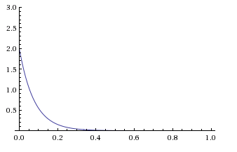
The equation is this:
CodeCogsEqn_1_ghmccn.gif


Where k is equal to 2583.3 (derived from the mass, back emf, and coil resistance)
m is equal to 200kg (the mass of the unit)
And v0 is equal to 2 (initial velocity)

Graphing this shows the ideal braking curve. Y axis being velocity in m/s and X axis being time in seconds

Graph_kfsjnh.png
 
Status
Not open for further replies.

Part and Inventory Search

Sponsor