Continue to Site

Eng-Tips is the largest engineering community on the Internet

Intelligent Work Forums for Engineering Professionals

  • Congratulations KootK on being selected by the Eng-Tips community for having the most helpful posts in the forums last week. Way to Go!

Electrical Symbol Question 1

Status
Not open for further replies.
Replies continue below

Recommended for you

Really - a panel enclosure has a schematic? What does a panel enclosure use the motor for?
 
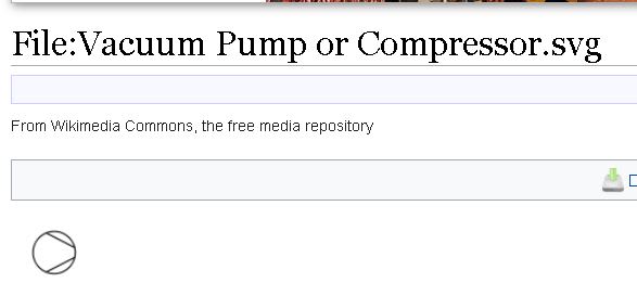
In hydraulic diagrams (maybe in pneumatic too - can't remember), that heavy chain-broken line style you see joining the motor and your mystery symbol denotes a mechanical linkage (meaning that the mystery symbol isn't electrical at all). If you take the surrounding circle off and cap the ends with straight lines, you end up with the P&ID symbol for a compressor.

Real-world engineering has to cross disciplinary boundaries, so it's no real surprise that real-world diagrams often end up being a bit polyglot.

A.

 
3DDave, that's not a schematic. It's a single line and it looks fine to me how it is.
 
I would interpret this symbol as a valve the motor to the left is an actuator. The dashed line between them is a mechanical link of some kind.

My posts reflect my personal views and are not in any way endorsed or approved by any organization I'm professionally affiliated with.
 
Lionel - thanks for the correction. It's a schematic diagram and it is a series of lines and arcs, not a single line.
 
0_zsltfx.jpg


Best Regards A

“Logic will get you from A to Z; imagination will get you everywhere.“
Albert Einstein
 
Dear Mr. PoliPoliCarps (Electrical)(OP)3 Feb 22 00:27
"...hello can someone please advise what device is in the red box symbol?..."
1. Info: E1 is a single-phase motor. It has only one on/off switch, for single direction of rotation/operation.
2. The solid -.- line shows the "mechanical" linkage to an external device.
3. The external device is the symbol of a pump/compressor. Note: which is a single directional operation device.
Che Kuan Yau (Singapore)
 
It's a schematic diagram and it is a series of lines and arcs, not a single line.

It's a single line, no matter what you claim. There is ONE single line feeding the transformer with a notation that there are 2 fuses on the primary. The 2 secondary lines show that only the live is switched, but if you didn't notice NONE of the lines connect to the ends of the coils of the transformer like they would on a schematic.
 
It's a diagram, not an electrical installation. It may represent a case where a single electrical power line is involved but being a pedant about the system it might represent doesn't solve the question of the item with the big red border around it that is the subject of the question.

To be clear - the original question was solely about what the one symbol meant. But thanks for ignoring that in favor of what neither I nor the OP was dealing with.
 
Unlike you being a pedant about the drawing having a single line and not a bunch of lines, and also your earlier pedant questions about how a panel enclosure can have a schematic or use a motor for something? And now you make an attempt at calling me out for posting what I did when you were already posting rather asinine questions? Maybe you actually don't know what a panel is, or what a single line is in which case you just shouldn't be responding at all instead of making fun of the OP.
 
I know what a panel is. Does a panel have a motor? I asked what the schematic was describing, but whoosh over your head.
 
Dear Mr.PoliPoliCarps (Electrical)(OP)3 Feb 22 00:27
"... hello can someone please advise what device is in the red box symbol? ..."
1. It looks like we are going out of the "cope" on the question asked.
2. Please refer to my post dated 4 Feb 22, 23:07.
3. Do you agreed or doubtful or have more questions. Our opinion are bona fides.
4. We look forward to your reply.
Che Kuan Yau (Singapore)
 
Status
Not open for further replies.

Part and Inventory Search

Sponsor