Eng-Tips is the largest engineering community on the Internet

Intelligent Work Forums for Engineering Professionals

  • Congratulations waross on being selected by the Tek-Tips community for having the most helpful posts in the forums last week. Way to Go!

Electronic Speed Control of a Generator 3

Status
Not open for further replies.

Dawsonh4

Chemical
Oct 4, 2020
58
0
0
US
I am trying to better understand methods that can electronically control the speed of a generator (specifically). The generator will be spinning using mechanical energy generated by air through a pipe. The electricity will be sent to a load or battery bank.

I thought a VFD might be the solution, but have begun second guessing if it is feasible. Another solution that may be adjusting the resistive load using a phase angle fired. A third option might be to use a controller such as ODrive (link). I am open to any input or suggestions.

For clarity sake - I know there are mechanical ways to control speed used on most large geneators (e.g., brakes, blade pitch, control valves), that are the preferred method due to efficiency. I am looking for electronic solutions due to surplus of energy and no control over the mechanical input.

Thanks in advance!
 
Replies continue below

Recommended for you

Motorcycles alternators run as total loss systems. They dissipate excess energy in the rectifier/regulator. There is no speed control.

If you want speed control, the dynamic braking routine is a VFD is likely your best choice. You'll be dissipating the excess energy as heat same as the above case.

Are you grid tied? You have almost unlimited ability sink power for profit into the grid.

These schemes are both very wasteful. Maybe a few addition details will help us steer you in a bette direction?
 
Thanks for the reply. The current assumption is that it is not grid tied, but tied to a battery bank. From my research the VFD would need to be tied to another motor in order for it to control the speed of the generator. Is that true?

Any experience with phase angle fired controllers? That seems to be an alternative.
 
If you are feeding a battery bank, why the obsession with speed control?
How big is this proposed generator? (kW)
20211015_150754_rjjvjy.jpg

This generator charges a battery bank.
No speed control.
The faster the generator spins, the greater the charging current and hence the load.
The voltage is almost directly related to the speed.
The voltage is limited by the battery voltage and thus the speed is regulated.
When an internal circuit sees an output voltage corresponding to full charge, the output is shorted internally and the generator stops.
This works dependably every day, supplying power to a water pump supplying water to a herd of beef.
When a proximity detector detects cattle near the water bowl, the pump is started.
Generally, the current draw of the pump will drop the voltage enough that the generator will start spinning again.
20211015_150737_geqny9.jpg

The generator is a three phase permanent magnet alternator with an internal bridge rectifier to outtput DC.

--------------------
Ohm's law
Not just a good idea;
It's the LAW!
 
Thanks for the input waross. I need to ensure that the generator does not put too much load on the prime mover (air through pipe) and does not rotate too fast.
 
What is your output? kW? Amps and Volts?
Diameter of the air pipe?
Purpose of the air pipe?
You won't get free energy.
Any energy that you extract from the air flow will have been supplied by the air source.
For speed, there are two main types of control.
1. Load bank. Initially the speed is controlled by the connection to the batteries. When the batteries reach full charge, a load bank is switched in in parallel with the batteries to dissipate the excess energy.
2. Shorting. When the batteries are at full charge voltage, the generator output is shorted internally and will stop.
The generator will cycle on and off depending on the battery state of charge.
I prefer the shorting method. Many less points of potential failure.

--------------------
Ohm's law
Not just a good idea;
It's the LAW!
 
VFDs are not loads, they are power converters. In order to control the speed, you have to control the energy out of the system, and that means controlling the load.

xnuke
"Live and act within the limit of your knowledge and keep expanding it to the limit of your life." Ayn Rand, Atlas Shrugged.
Please see FAQ731-376 for tips on how to make the best use of Eng-Tips.
 
How tight do you need to control speed?
Since power in a resistor is V^2/R, if you used a DC generator with fixed excitation the voltage would vary with speed - as the voltage increased the load would increase by the square. This would in effect control speed - if you used a variable resistor you should be able to manually set a rough speed.


Just a thought.
 
That was a failed attempt to post a screen shot.
Sorry.
I did some trouble shooting on the installation in the first pictures.
The rancher is very happy with it.
The wind turbine and the solar panels are working well together.
He did have a problem with the inverter shutting down on low battery voltage.
He added a second set of batteries and has enough carry-over time now.
The cattle tend to water in bunches and the continued use was draining the battery bank.
There was enough energy available in 24 hours and a larger battery bank gave the carry-over to avoid the low voltage shutdowns.

--------------------
Ohm's law
Not just a good idea;
It's the LAW!
 
I wanted to give this a bump to see how things would change if the generator was AC instead of DC. Any input would be appriciated!
 
Well, unrectified AC won't charge a battery.
But, a DC generator has issues with brushes.
The Primus generator generates three phase AC, avoiding brush and commutator issues.
The AC is bridge rectified internally to DC for battery charging.
As the wind speed increases, the output voltage rises.
As the output voltage rises above the battery voltage, the current increases.
As the current increases, the load on the prop increases.
These factors all work together to control the speed of generator within acceptable limits.

--------------------
Ohm's law
Not just a good idea;
It's the LAW!
 
Here's a basic description of how an electromechanical generator works:
[ol 1]
[li]The prime mover (e.g., turbine, engine, etc.) produces torque on the generator shaft.[/li]
[li]This spins the generator rotor, which has a magnetic field on it produced by an excitation system (i.e., it typically has an electromagnet on it).[/li]
[li]The magnetic field cuts the conductors in the generator stator, inducing a voltage in those conductors per Faraday's law.[/li]
[li]When connected to a complete output circuit with a load, current flows out of the generator due to the voltage it produces.[/li]
[li]The output current of the generator produces a countertorque (per Lenz's law) on the shaft connecting to the prime mover. This reduces the speed of the prime mover/generator combination and the associated electrical frequency (AC) or voltage (DC) until a constant speed is achieved for a given mechanical power in and electrical power out.[/li]
[li]Voltage (in an isolated AC system or a DC system) or reactive power (in an AC system with a parallel generation source) in the electric circuit in the usual case is controlled by manipulating the generator excitation using a voltage regulator as electrical load varies. Alternatively, these parameters could be regulated by manipulating the load (load bank, export more power to the grid, etc.)[/li]
[li]Frequency (in an isolated AC system) or power (in an AC system with a parallel generation source) in the electric circuit in the usual case is controlled by manipulating the mechanical power output of the prime mover using a governor as electrical load varies. Alternatively, these parameters could be regulated by manipulating the load (load bank, export more power to the grid, etc.) or by manipulating both the generator and the load.[/li]
[/ol]

Items 1-6 also apply to a DC generator (apart from the associated electrical frequency mentioned in Item 5 which is zero).

Speed control is only achieved when the mechanical input power equals the sum of the mechanical losses, electrical power output, and electrical losses. Otherwise, the machine accelerates.

xnuke
"Live and act within the limit of your knowledge and keep expanding it to the limit of your life." Ayn Rand, Atlas Shrugged.
Please see FAQ731-376 for tips on how to make the best use of Eng-Tips.
 
Thanks Xnuke!

Could you elaborate on the types of devices that would regulate the voltage? I have been doing a bunch of research on Odrive which is a field oriented controller. Would this be a possible solution? What about a VFD?
 
This problem is similar to regulating the speed of a car with a motor at wide-open-throttle but not by touching the throttle.

Want to limit the speed? Burn off excess energy as heat.

Unless you want to melt the VFD into a puddle of garbage using it as a short circuit it won't help. VFDs work by stopping power going to a motor - but the power coming to the generator is an unlimited/unregulated amount from the air supply. So, add a valve to the air supply to limit the power coming in. Oh, right, that's a solution that has already been dismissed.

So, take the VFD and stuff it into the generator to act as a brake. That will let you meet the goal of using a VFD and will allow regulating the speed of the generator. Problem solved.

If a VFD would work to regulate speed when air isn't limited this would not have happened: They depended on a brake, which failed.
 
What about a VFD? What do you mean by "Field Oriented Controller"?
Your links to Odrive aren't opening for me.

There are a few niche applications for load control of voltage.
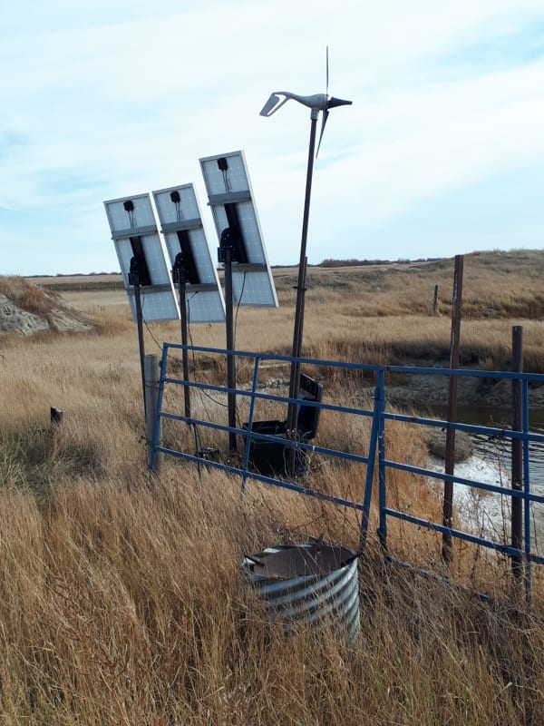
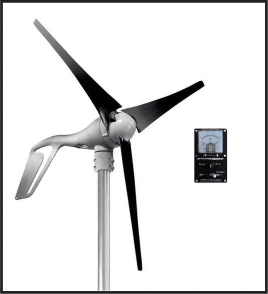
The Primus is one such.
Using the batteries for load control allows different sources to operate in parallel.
This may more than one Primus turbine generator in parallel or, as in my example, a Primus generator working in parallel with solar panels.
Load control of an AC generator has some drawbacks.
<Anecdote alert.>
An engineering firm approached a remote indian reserve and proposed replacing their diesel generator with a hydro-electric generator.
The plan was to run the water turbine full out with no control on the water flow.
Speed or frequency would be controlled by switching in more or less load.
For a load bank they proposed building a laundromat and using the waste energy to heat the water.
They installed a very large hot water tank, with a large number of heating elements.
The control would switch on or off heating elements as needed to use any excess energy and thus control the frequency.
So, not only free electricity but free hot water for the laundromat.
The Department of Indian Affairs was happy to finance the project.

Then reality struck.
I had a lot of friends in the area and was quite interested in the system.
I dropped in to the engineering office in the city and the folks there were happy to talk about their pet project.
I asked how the size of the generator was determined.
"Well, the Department of Indian Affairs requires a full engineering study for installations over 50 kW,so by that criteia, we selected a 50 kW generator.
That was the first mistake.
50 kW was not enough for the demand of the community.
There was chronic issues with very low voltage and frequency.
Normally, it would be simple to set up the hydro control for base load and adjust the diesel control for peaking control.
BUT
NOT WITH LOAD CONTROL.
Either the hydro or the diesel, but not both together.
I passed through later that year.
As I entered the community I could hear the diesel running. The system had been barely usable during the day and they had been switching to the generator for the evening peak ;oads.
I met one of the elders and asked him what was wrong.
"NO Water.
If they had asked, we could have told them that that creek goes dry every summer."
<Anecdote off>

Do you realize that some of us have studied for several years to learn the basics of generation and control?
A great many generator are speed controlled by a variation of a PID controller. That Proportional-Integral-Derivative.
Almost all use a Proportional control. Some use Proportional + Integral.
The basics of PID control may warrant at least a semester of study, possibly more.
The construction and application of PID controllers is more involved.
PID controllers may be mechanical, pneumatic, or electronic.
The input may be any thing that may be quantified:
Speed,frequency, heat, voltage, pressure, current, Watts, mechanical position.
One a variable has been quantified, the input to the PID may be direct mechanical, a pneumatic signal. (3 to 15 psi was common.)
The input may be a variable current.
The output may be a variable voltage.
The output may be a variable pneumatic signal.
The output may be a variable mechanical position.

Trying to cram several semesters of study into some questions and answers on a free internet site may not be productive.

Why not hang a prop on an automotive alternator?
Select an alternator with a built in voltage regulator.
It will operate over a range of a few hundred RPM to a few thousand RPM.
It is optimized for charging batteries.
When the barreries are fully charged, the voltage regulator will remove the field excitation and the generator will spin free.


--------------------
Ohm's law
Not just a good idea;
It's the LAW!
 
Status
Not open for further replies.
Back
Top