Eng-Tips is the largest engineering community on the Internet

Intelligent Work Forums for Engineering Professionals

  • Congratulations waross on being selected by the Tek-Tips community for having the most helpful posts in the forums last week. Way to Go!

Electronic Speed Control of a Generator 3

Status
Not open for further replies.

Dawsonh4

Chemical
Oct 4, 2020
58
0
0
US
I am trying to better understand methods that can electronically control the speed of a generator (specifically). The generator will be spinning using mechanical energy generated by air through a pipe. The electricity will be sent to a load or battery bank.

I thought a VFD might be the solution, but have begun second guessing if it is feasible. Another solution that may be adjusting the resistive load using a phase angle fired. A third option might be to use a controller such as ODrive (link). I am open to any input or suggestions.

For clarity sake - I know there are mechanical ways to control speed used on most large geneators (e.g., brakes, blade pitch, control valves), that are the preferred method due to efficiency. I am looking for electronic solutions due to surplus of energy and no control over the mechanical input.

Thanks in advance!
 
Replies continue below

Recommended for you

Yes AC motors are usually speed controlled by varying the frequency.

Pretty much all of the frequency based speed controllers for 3-phase AC motors (or brushless DC or permanent magnet rotor) turns DC into AC and are capable of generating back into the DC source, either charging batteries or capacitors. The trick is turning this energy being pumped into the DC source into something useful. You can either use the DC directly or you need some kind of inverter that can create AC you either use islanded or put back into the grid.
 
I am starting to get a beginners handle on how to control load to a DC generator thanks to this forum. Would anyone be able to comment on methods to control frequency on AC induction/synchronous generators and if you can also control these generators with load?
 
Go big or go home.
One example that may have a distant parallel to your questions is the operation of a recovery boiler.
In a Kraft pulp mill, A solution of caustic compounds called white liquor is used to dissolve the substances binding the wood fibres together.
Then it becomes black liquor.
Black liquor will put out most normal fires, but if a fire is big enough and hot enough, black liquor will burn.
The black liquor is burned in a special boiler called a recovery boiler, where both the caustic compounds and energy are recovered.
Steam is generated in an old design recovery boiler at 800 to 1000 PSI. Newer designs may develop pressures of over 2000 PSI.
A pulp mill has need for steam at around 100 to 150 PSI, and steam at around 15 PSI, but no need for high pressure steam.
The high pressure is directed to a two stage expansion turbine driving a generator.
On I worked on was rated at 40,000 kW or 50,000 HP.
I did say go big!
Steam is admitted to the first stage and the pressure is dropped to around 150 PSI. The volume of steam is controlled by the need for 150 PSI steam.
The generator absorbs the energy developed by the expanding steam.
Some of the 150 PSI steam is passed through to the second stage of the turbo-expander. Steam exits the second stage at around 15 PSI.
The steam entering the second stage is part of the gross steam entering the high pressure stage.

The generator recovers or converts all of the energy difference between high pressure steam and low pressure steam into electrical energy.
The caustic compounds drift down in the boiler and accumulate in a molten pool at the bottom as green liquor.
Water is added and green liquor becomes white liquor and is reused.
A pulp mill uses a lot of electrical energy, more than is generated by the recovery process.
So the output of the recovery turbo-generator reduces the quantity of electricity that the mill must purchase from the utility.
The generator output is controlled by the quantity of lower pressure steam needed by the pulping process.
While the financial considerations may be different, the operation of the turbo-generator is similar to a utility generator operated in base mode, or a "Run of the River" hydro-electric installation.
The generator absorbs the energy available and the output varies as the amount of available energy varies.
You keep asking about "The load controlling the generator".
Try thinking about it as the generator controlling the load.
How much do you want to reduce the air pressure? How can the generator control that reduction.

--------------------
Ohm's law
Not just a good idea;
It's the LAW!
 
The scale of "Go Big or Go Home!"
To compare a recovery turbo-generator to your application, compare a hand-full of wheat kernels to a couple of thousand acres of mature wheat fields.
The principle is similar. Using a generator to reclaim otherwise wasted energy.

--------------------
Ohm's law
Not just a good idea;
It's the LAW!
 
Thanks for the real world example.

I am still unsure on methods to control frequency on AC induction/synchronous generators and if you also need to control these generators with load in order to affect rotational speed/torque.
 
On stand alone standby generator, the governor controls the speed between 100% of rated speed at full load to 103% of rated speed at no load.
There are exceptions, but those settings have worked well for years.
Grid tied generator governors control between 100% at no load and 105% at full load, but they don't.
That is The governor is configured to control between 100% and 105% (5% droop), but the grid locks the speed at 100% plus or minus small variations.
So how do you control the load? With the governor set at 100%, the generator idles on-line but doesn't contribute any energy.
As the governor setting is increased, the generator picks up load until at a governor setting of 105% the set is developing rated output.
When many generators are connected in a grid, one generator, called the swing set, responds to load changes on the grid.
All of the other generators run at fixed output.
If the load on the swing set is dropping too far, or rising too far, load dispatch will cause one or more of the base load sets to reduce their output or to drop off line.
A long time ago, I was visiting a very old hydro plant. The generators were running at about 10% output.
Running at low output is better than shutting down completely. It keeps the alternators warm and dry.
One operator was on duty.
The phone rang.
It was the load dispatch center.
"Please take your sets up to 80% load."
The plant was so old that everything was manual. There was not even an Automatic Voltage Regulator.
The operator turned a switch on the control board.
WE could see on the machine room floor, a very large hydraulic cylinder start to extend and push on a very large bell crank.
That opened the gate and allowed more water to flow through the turbine.
As the output increased without a corresponding increase in excitation, the power factor dropped. (On a stand alone set, the voltage would drop, but when connected to the grid, one set has little control over grid voltage and the PF drops instead.
The operator left the switch controlling the hydraulic solenoid and moved to a rheostat.
He manually increased the excitation until the PF was satisfactory.
Back to the hydraulic control and pick up more load.
Over to the rheostat and increase the excitation.
Rinse and repeat.
It was a unique experience to see operations that are normally done automatically done completely manually.
A few years later the plant was completely automated and there was no longer a local operator. Everything was done remotely by the load dispatch center.
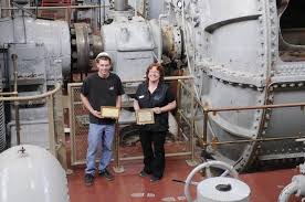
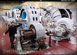
The plant was eventually taken out of operation and became a visitors center.
[URL unfurl="true" said:
https://dbpedia.org/page/Stave_Falls_Dam_and_Powerhouse[/URL]]Stave Falls Dam is a dual-dam power complex on the Stave River in Stave Falls, British Columbia, Canada. The dam was completed in 1912 for the primary purpose of hydroelectric power production. To increase the capacity of Stave Lake, the dam was raised in 1925 and the Blind Slough Dam constructed in an adjacent watercourse 500 m (1,600 ft) to the north, which was the site of the eponymous Stave Falls. In 2000, the dam's powerhouse was replaced after a four-year upgrade. The original Stave Falls powerhouse was once British Columbia's largest hydroelectric power source, and is a National Historic Site of Canada. (en)

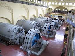
MACHINE_FLOOR_mkrr3p.jpg


HERE IS THE ORIGINAL TURBINE HALL

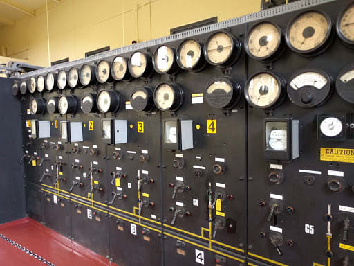
2016-06-13_kzuqqm.jpg


THE ORIGINAL MANUAL CONTROL BOARD

images_fm3egx.jpg


RELATIVE SIZE


EXCITER_GENERATOR_rn4tra.jpg


EXCITER GENERATOR AND WATER WHEEL DRIVING IT

--------------------
Ohm's law
Not just a good idea;
It's the LAW!
 
For more information, GOOGLE, All: stave falls dam and powerhouse
For more pictures, GOOGLE, Images: stave falls dam and powerhouse

--------------------
Ohm's law
Not just a good idea;
It's the LAW!
 
When I started at my company on 2007 they still had an underground hydro powerhouse with the original rotating armature machines from 1898. It was all manual as well, they used rheostats on a 125DC bus to control voltage, and the operator performed all the starting, synchronizing and loading manually.
I’ve personally never need an AC machine controlled with load, generally because the AC machine is set to control frequency, and it’s generally easiest by controlling incoming mechanical power from the prime mover.
 
Status
Not open for further replies.
Back
Top