mechdrive1
Mechanical
Hello All!
I am trying to drill through an Al 6061 alloy layer (1.5mm thick) with a rigid tool (steel alloy). I have used Johnson-Cook plasticity model for both aluminum layer and tool. Also, to remove the elements I have specified JC damage model for aluminum layer with displacement based damage evolution. The aluminum layer is constrained (ENCASTRE Boundary Condition) on the side surfaces while all the other surfaces are free. The feed rate of tool is 260 mm/sec (artificially increased) to reduce computational time and rotational speed is about 8000 rpm. The JC model constants are as follows:
for tool:
*Plastic, hardening=JOHNSON COOK
1.15e+09, 7.39e+08, 0.26, 1.03, 1723.15, 293.15
*Rate Dependent, type=JOHNSON COOK
0.014,1.
for aluminum layer:
*Damage Initiation, criterion=JOHNSON COOK
0.071, 1.248, -1.142, 0.147, 0., 855., 293.15, 1.
*Damage Evolution, type=DISPLACEMENT
0.67,
*Plastic, hardening=JOHNSON COOK
3.35e+08, 8.5e+07, 0.11, 1., 855., 293.2
*Rate Dependent, type=JOHNSON COOK
0.012,1.
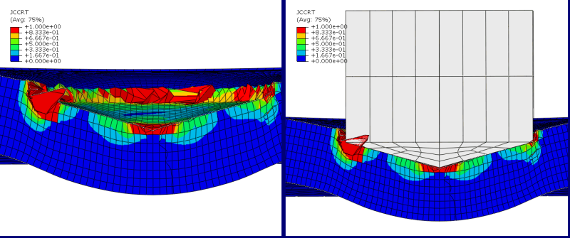
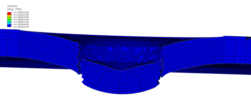
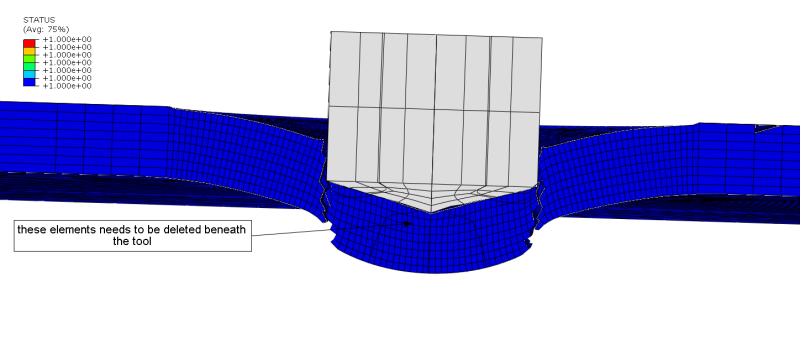
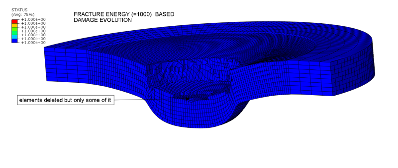
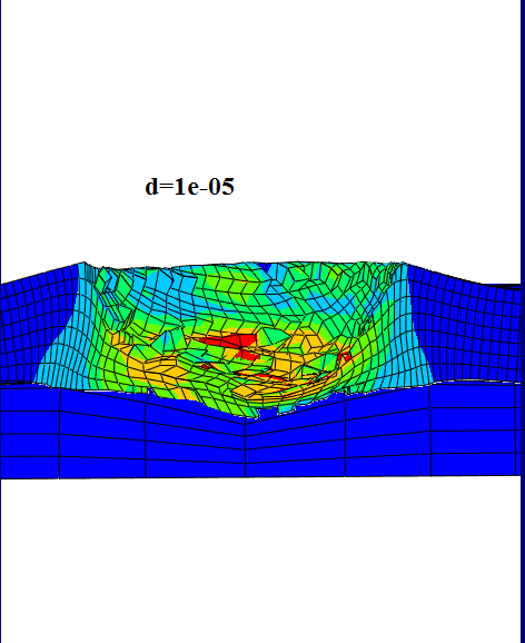
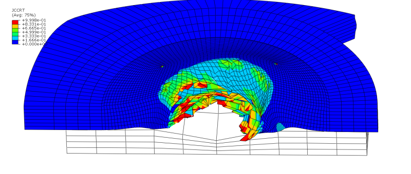
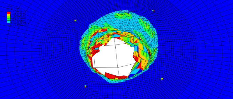
The elements are not getting deleted as it should have been instead the layer is getting displaced in the direction of tool movement (like compression). There is element deletion but not too extensive and not beneath the tool where it should be. I have tried using different values for displacement in the damage evolution criteria but nothing has worked so far.
I am attaching the input file for your reference. Any kind of feedback/clarification is welcome. Can anyone help with the element deletion please?

