Eng-Tips is the largest engineering community on the Internet

Intelligent Work Forums for Engineering Professionals

Element Failure

Status
Not open for further replies.

cirokos

Civil/Environmental
Apr 11, 2022
63
0
0
GR
Hello everyone,

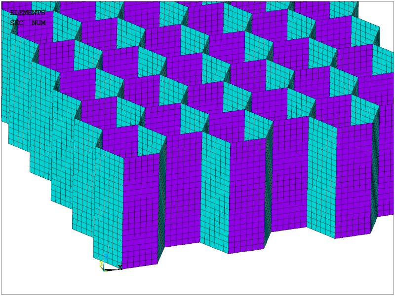
I am modeling a structure with shell elements in mechanical APDL. My problem is that the solution stops due to excessive element distortion in very low displacements thus giving unwanted results. Elements on the edges show this problem but not on the inside.
I cannot find a way to overcome this problem.
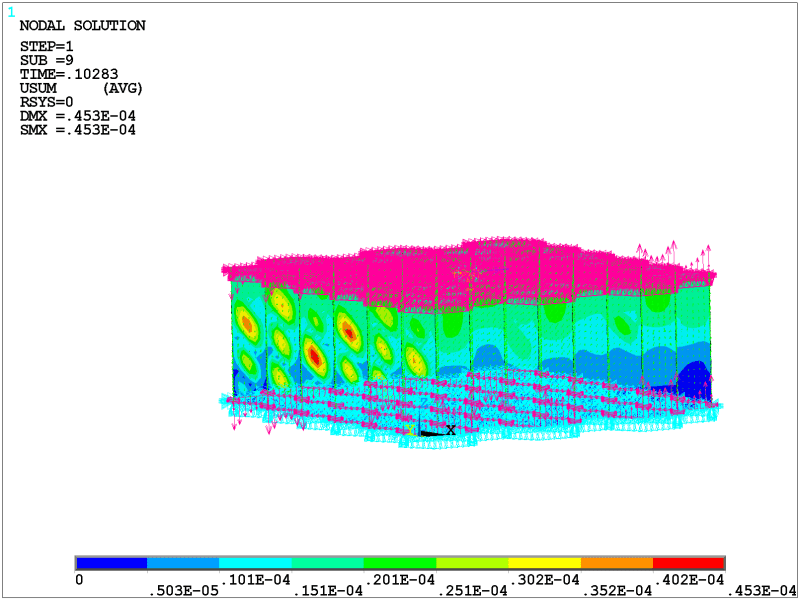
At the top, I have created a rigid region; at the bottom, it is constrained at all translational degrees of freedom. Displacement control implemented at a MasterNode

Here is a photo of the model.


testing6002_b7vyod.png
 
Replies continue below

Recommended for you

Yes, it seems that the mesh itself doesn't cause this problem. Are those distorted elements located anywhere near the rigid region or boundary condition ? If you want to simulate crushing of this honeycomb, doing it with the help of rigid surfaces might be a good idea.
 
No all of the elements appear to be approximately in the middle of the height(where the red areas are) and I want to simulate the shear deformation of the core.
 
those displacement patterns look suspiciously like shear buckles ?

what code is "mechanical APDL" ?

Have you tried to model a flat sheet with shear buckling ?

"Hoffen wir mal, dass alles gut geht !"
General Paulus, Nov 1942, outside Stalingrad after the launch of Operation Uranus.
 
I would take a closer look at the (scaled and unscaled) deformed shape of the model, especially at the locations of those distorted elements. Perhaps the material stiffness is too low by a mistake.
 
So the red areas in your first picture are the ones with high distortion? If so, then that is exactly expected for this loading. The cell walls buckle in shear. Are you running geometric nonlinear analysis?
 
have you tried modelling a test case ... a flat sheet, maybe with edge stiffners ... something you know the answer to so you can confirm ANSYS is correct (or that your modelling is correct).

"Hoffen wir mal, dass alles gut geht !"
General Paulus, Nov 1942, outside Stalingrad after the launch of Operation Uranus.
 
what's your element size ?

"Hoffen wir mal, dass alles gut geht !"
General Paulus, Nov 1942, outside Stalingrad after the launch of Operation Uranus.
 
cirokos - you have been messing with this hex core FEM for months now. What is the purpose of the modelling? MS/PhD project? Surely a company is not paying you to spend all this time on it when one could just look up the core shear strength in the Hexcel core datasheet.
 
circos,

When I read your posts I noticed someting that I find a bit confusing. In the first post you say the the distorted elements are at the edges, in a later post you say that they are at the center (middle of height). Are the problems near or far away from the boundary conditions? Because rigid zones can cause issues with convergence.

One option can be to "soften" the rigidity and see if that helps the solution. One way to do that can be to use springs in the supports.

Also, what is the purpose of this analysis? What are you investigating?

Thomas

 
To everyone.

Thanks a lot for your help, I really do, you have given me some great advice!

Unfortunately, I couldn't come to a conclusion on the problem with the model/analysis.
The experiments were accurate and there is no doubt about that. I could share the code with anyone that's interested or wants to have a look and maybe figure out the problem.

This project was part of my undergraduate studies and my personal interest.

Thanks again a lot!
 
"This project was part of my undergraduate studies and my personal interest." ... sigh ... student posts are not permitted. This is for professionals.

"Hoffen wir mal, dass alles gut geht !"
General Paulus, Nov 1942, outside Stalingrad after the launch of Operation Uranus.
 
Status
Not open for further replies.
Back
Top