In conventional FE packages there are generally lower and higher order elements. Lower order elements have nodes at the vertices whereas higher order elements have additional mid-side nodes. As the elements are iso-parametric, the nodes define not only the shape of the element but also the nature of the displacement field assumed to be in the element. With the three noded triangle the shape is the basic triangle with straight lines between the nodes. The displacement field is defined be three parameters which multiple the first three terms in a Pascal triangle of two dimensional functions, i.e., 1, X and Y. The displacement field is thus complete in a linear sense. The strains are the gradients of the displacements and so for the three noded triangle these must be constant.
Four the four noded quadrilateral element there is an additional coefficient available and this multiplies the XY term of available quadratic terms. As the X^2 and Y^2 terms are not used then the displacement field is complete in the linear sense but incomplete in the quadratic sense. The strains then are slightly better than constant as there will be the linear term associated with the quadratic displacement term. It is not, however, the case, as suggested above, that the strains are fully linear.
A finite element model approximates the solution to a real problem. If the stress/strain field for the real problem is constant then both elements will give the correct and exact answer to the problem. In general, however, the true stress/strain field will not be constant and will more likely be rather non-linear - think of a beam in bending for example. In this case the elements cannot model the true solution and the engineer needs to use mesh refinement to converge towards the true solution - think of approximating a general curve with piecewise constant functions, the more elements you use the more accurate will be your solution.
The same situation applies to the higher-order elements with the quadrilateral element having two additional nodes which give a slightly better potential approximation of the true stress/strain field.
Thus, I would say that there is no particular concern with using triangles rather than quadrilaterals. The reason that triangles are used more often is that the mesh is generated automatically and it is easier to generate triangles than quadrilaterals. If the mesh is to be generated by hand then I would generally attempt to do it using quadrilaterals since there is the small advantage noted above and it is also easier to perform uniform mesh refinement of the sort required in convergence studies.
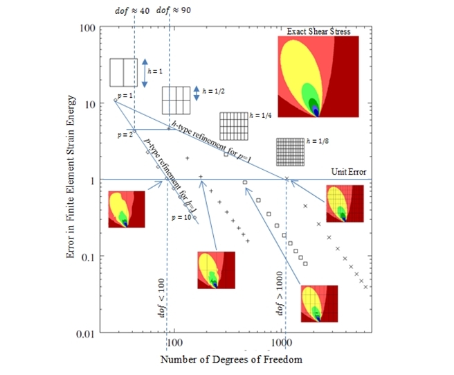
I would also point out that unless there is any indication to the contrary, then higher order elements should be used. These adopt a higher order displacement field and in terms of computational efficiency perform significantly better than their lower order equivalents:
There is much that you can do yourself to increase your understanding of how the various element types perform. There are many problems available which have theoretical solutions and you can model these with your FE system to see what sort of mesh is required to achieve a reasonable level of engineering accuracy. To this end, the following article might be of interest to you: