Eng-Tips is the largest engineering community on the Internet

Intelligent Work Forums for Engineering Professionals

Elevated PEMB Design with Hairpins 2

Status
Not open for further replies.

BG1999

Structural
Sep 3, 2024
4
0
0
US
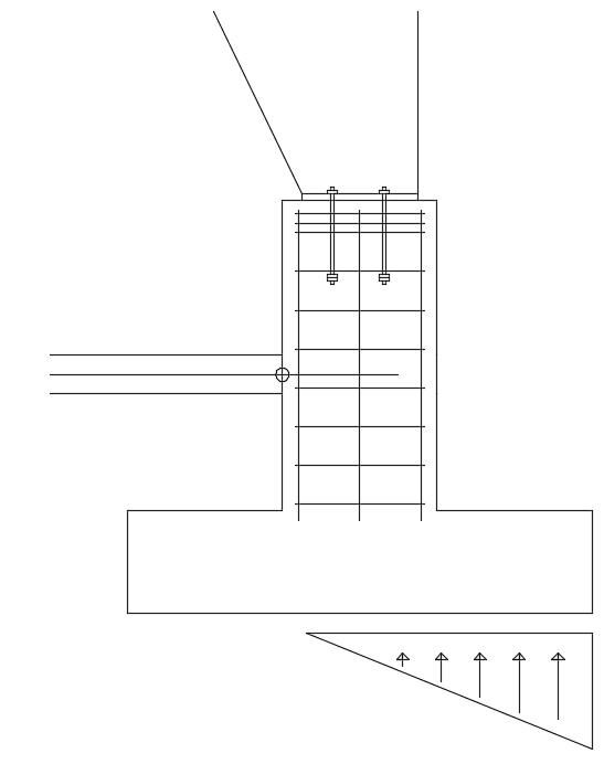
I have been working on a spreadsheet to help design footing sizes for PEMB's and I have come across an issue when the building columns are not at slab level. The company I work for uses hairpins to resist the kickout thrusts from the mainframes, but I am not quite sure how this works when the frames are up 2' for instance. My thinking is to make the pier strong enough that it can transfer the total horizontal thrust into the hairpins. I am also thinking that the rotation occurs about the point where the hairpin meets the slab. I have attached a sketch of the situation I am talking about with a circle around the point where I think rotation occurs. This is the point I am summing moments about in order to find the soil pressure.
I would love to hear if anyone has experience doing this and what the approach you took was or if there were any design guides that you found useful.
Thanks!

Capture_cbg8ak.png
 
Replies continue below

Recommended for you

I have done this a few times, but with grade beam tension ties rather than hairpin/slab tension ties. You just have to follow the statics and draw a good free body diagram to capture the lever effect. I think Newman's PEMB foundation book has a design example for this type of situation.
 
I agree with bones206. I haven't seen, nor designed one as shown above to date and typically avoid this at all costs due to concrete breakout calculations for the thrust loading.
 
Ausur, if the anchor bolts were extended down to where the hairpin is located would you still be worried about concrete breakout? I am struggling to see how a grade beam with tension ties would be much different from this design.
 
I would still check the footing rotating about each of the sides at the bottom of foundation level.

The pilaster can be reinforced and sized so that you can get the shear into the hairpins pretty easily.

Curious how the load from the hairpins is resisted. Generally I assume it's resisted by friction on the slab itself. Recently I've seen designs that used fairly short hairpins into an unreinforced slab and I don't know how that load path is supposed to work.

 
[sub]
BG1999 said:
Ausur, if the anchor bolts were extended down to where the hairpin is located would you still be worried about concrete breakout? I am struggling to see how a grade beam with tension ties would be much different from this design.
[/sub]

Yes - While you could design the concrete to transfer the force to the hairpins, simply extending the anchors down to the hairpin won't do it. Your method of force transfer here is applying a shear load to the top of the concrete, which requires checking for concrete breakout. This typically controls, especially for many of the thrust forces I have seen on larger PEMB's. I'm not saying it will always fail, in fact you can get some good capacities with the right concrete strength, even get a bit more with proper reinforcing detailing to provide shear breakout reinforcing. Once you have the force into the pier, you then have a cantilever element with a pin at the slab and a pin at the footing, so there is an aspect of rotation or shear on the footing as well, depending no how you design it. For a simple concrete breakout check, put the anchors in Simpson Anchor Designer, or Hilti Profis with the pier size, anchor embed and put supplemental reinforcing as A to account for reinforcing and see what happens with a large thrust load.

A grade beam with tension ties has a direct transfer mechanism as the grade beam is typically at the grade, flush to the bottom of the anchors and results in more concrete around the anchors for breakout while allowing transfer directly from anchors to the grade beam ties. When elevated, the anchors themselves go into bending resulting in breakout.

As driftlimiter said, you can size and reinforce the pedestal for transfer easily, but don't expect to always have a tiny pedestal.

Note, I would love for you or someone else to prove me wrong here as it could help in many ways with concrete design.
 
I agree with Aesur, breakout would still need to be checked since the hairpins/grade beam is 24" below the top of pier.

Adding those hairpins may help with the footings if sliding or overturning is causing them to size up a lot, but it wouldn't help with the pier size.
 
This type of foundation is really sub-optimal for PEMB frames. Ideally you want the thrust force line of action to coincide with the tension tie. I try to talk architects out of this arrangement, but usually lose that battle and end up designing a monster foundation.
 
I'd design the pier as a column with the thrust load at the top and a fixed based where the hairpin will be. As long as the pier is solid enough to handle the moment at the base, the thrust will get translated into tension in the hairpin.
 
Thanks for all of the replies. I agree that this type of foundation is not ideal for PEMB frames but there are some clients who want this look and there is no getting out of it. I have taken IlliniPE's approach and designed the pier as a column and the results that I am getting seem reasonable. The question I am left with is, how does this system really behave? When a thrust load is applied will the footing try and rotate about the base or will it rotate about the connection at the hairpins? My thought is that it will rotate about the hairpin connection, so summing moments there will allow me to calculate the soil pressure.
Any thoughts on this?
Thanks again, I appreciate the time taken to respond.
 
The footing tries to overturn yes. I sum the moments about the base of the footing at either extreme end for stability checks. I dis-agree with summing the moments about the hairpin connection point. However I include the hairpin reaction in my sum of the moments about the bottom corner of the footing as a resistance to the applied moment.

For stability checks I utilize the weight of the footing, pilaster, soil above the footing, tributary weight of the grade beam (properly design grade beam for flexure) as well as skin friction on the footing and grade beam.

For soil checks I use net bearing pressure and include only the applied loads (no weight of concrete).
 
BG1999:

There are a few ways look at this, but I'd say the most realistic is to not think of the hairpin as a hard support point instead it will be more spring like and really just restrain the overall top deflection of the pier so something like a fixed base - spring - cantilever model is probably an ok approximation.

Here are 5 quick free bodies with approximately proportional properties and the deflections and moments plotted:
[pre]fixed-roller-cantilever fixed-spring-cantilever spring/rotational spring - spring - cantilever
pin-roller-cantilever pin-spring-cantilever[/pre]

Capture_i4leuq.jpg


The spring at the slab is AE/L assuming a 10ft wide x 4 in thick effective beam , 3000 psi, and a 60 ft span
 
I think I have generally done it the other way. I'd tend to use springs everywhere, but if I needed to simplify I'd be using a rotational spring for the footing base and a solid roller for the concrete tie, and if I was using springs everywhere I'd likely overestimate the tie stiffness to be safe. Taking the base as fixed and the concrete tie as a spring is going to underestimate the load on the tie.

Shallow foundations like this are really really flexible under moment when you start considering the soil and are likely going to move way before the concrete tie does. You'll have a bunch of theoretical capacity in the footing, but you're going to break that tie before you mobilize all of that capacity.

It's annoying, because it's likely that the most efficient way to do this kind of construction is to design the base of the column to take the small amount of moment necessary to put the pin at the base of the footing, but you're never going to get the vendor on board to do it.
 
TLHS:
Good point, after more thought I would tend to agree that the tie will be stiffer than foundation sliding/passive resistance (silly me otherwise you wouldn't need to use the tie). The foundation rotational stiffness will depend on the footing size but since the PEMBs are all about low cost you'd be aiming for the smallest foundation so a soft rotational spring if used does make more sense.
 
Status
Not open for further replies.
Back
Top