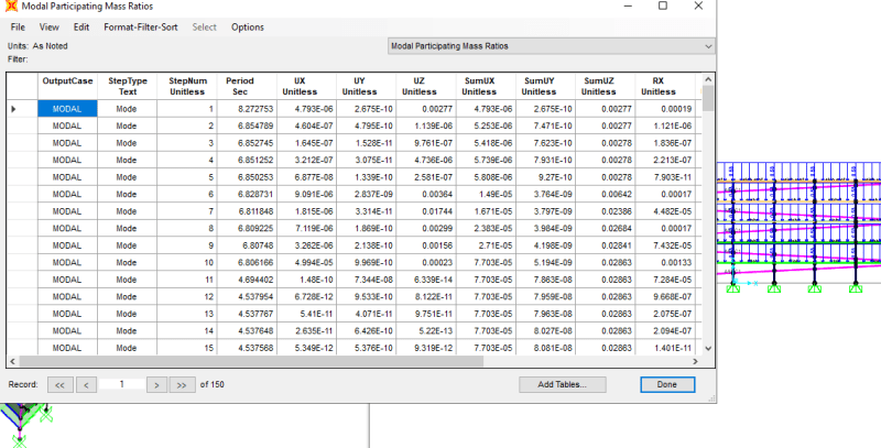
I ran a ELF analysis on a model in SAP 2000(Special Moment Frame, h= 60ft). The base shear and global z reaction for each of the loadings is near what I calculated on my Excel. However, My period is different under the mode where I get 90% mass participation in each direction. The period calculated by the program is T= 0.39s whereas my excel calculations got Ta= 0.64s. Can I accept this?
Navigation
Install the app
How to install the app on iOS
Follow along with the video below to see how to install our site as a web app on your home screen.
Note: This feature may not be available in some browsers.
More options
Style variation
-
Congratulations MintJulep on being selected by the Eng-Tips community for having the most helpful posts in the forums last week. Way to Go!
You are using an out of date browser. It may not display this or other websites correctly.
You should upgrade or use an alternative browser.
You should upgrade or use an alternative browser.
ELF Procedure Period Question 1
- Thread starter Respawn
- Start date
- Status
- Not open for further replies.
jochav52802
Structural
Hello Respawn,
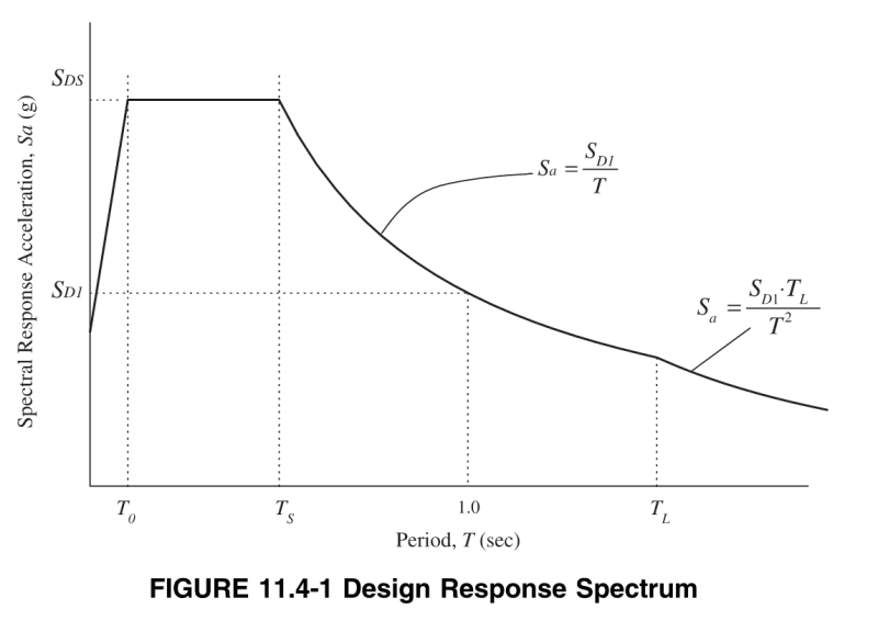
Per ASCE 7-16, Section 12.8.2, you can use either your structural analysis to calculate the period or the approximate period equation 12.8-7, as long as your result doesn't exceed the upper bound specified in Section 12.8.2.
Hope that helps!
Per ASCE 7-16, Section 12.8.2, you can use either your structural analysis to calculate the period or the approximate period equation 12.8-7, as long as your result doesn't exceed the upper bound specified in Section 12.8.2.
Hope that helps!
-
1
- #3
Provide a screenshot of the period results and mass participation. They should be much closer for the first mode. Did you use Rayleigh method for your excel check?
The fact you said "However, My period is different under the mode where I get 90% mass participation in each direction." suggests your 0.39 seconds isn't the first mode, but the one at which the sum of mass participation reached 90%?
The fact you said "However, My period is different under the mode where I get 90% mass participation in each direction." suggests your 0.39 seconds isn't the first mode, but the one at which the sum of mass participation reached 90%?
- Thread starter
- #5
- Thread starter
- #6
So as you'll note the first 15 modes you showed are all greater than 4.5 seconds. So I suspect something is fundamentally wrong with your model.
Also as suspected the mode at which 90% mass participation is meet for each fundamental direction of the response is not the fundamental period T1. The fundamental period T1 is the period with the highest mass participation for a given direction. Not the period corresponding to the sum of mass participation being 90%. Usually if you address all the bits flapping around causing the larger periods, you'll find the first couple of translational periods will be the fundamental 1st mode periods for each direction of loading.
Start with reviewing the mode shapes for these modes (animate them to see what is causing the higher periods). You likely have many issues with the model that need to be sorted. I'd also check the analysis log for issues such as being ill conditioned. Also if you run the model with the standard solver it will give you the coordinates of locations that are potentially causing issues.
This issue with CSI software is even if there are significant errors in your modelling it still appears to solve in a manner that leads you to believe it is correct. You need to review the model and logs to decide if the results are valid.
Let us know how you get on.
- Thread starter
- #8
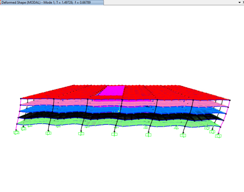
You can look at your mode shapes in SAP. Just show your deformed shape and select mode. That may be enough to see what is moving with the first few modes. If not, there is a button at the bottom right that is called start animation which will show how each mode moves around. It seems most likely that there is some element that is not connected the way you intended and is flopping around causing those long periods. It is also possible that you modeled something that is super flexible compared to the rest of your structure (like a flagpole or antenna)
- Thread starter
- #10
So then back to your original question, you are allowed to use your fundamental period from analysis which is capped at CuTa per ASCE 7-16 Section 12.8.2. You are also allowed to continue using Ta, but it is generally going to be conservative. On a similar note, the approximate period calculated via equation 12.8-7 should almost always be lower than the period you get from analysis because it is supposed to be a conservative assumption (remember that in general the lower your period, the higher your acceleration)

- Thread starter
- #12
The reason the cap exists is because a lot of the time your model's period is higher than CuTa - that is ok. The cap only limits the period that you plug into the base shear equation. So in your case, you can plug T=0.9 sec into the base shear equation instead of T=0.64 sec. Then you apply that base shear to your model.
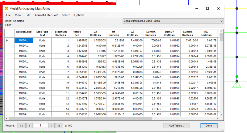
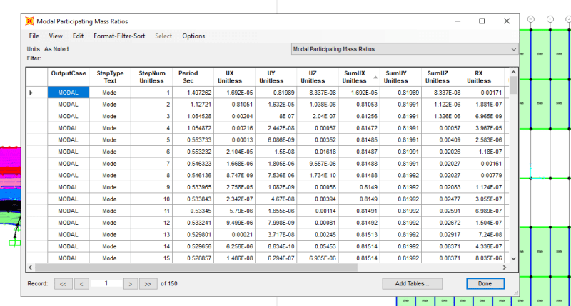
Your updated results still show the mode 3 as 1.12s with 80% mass participation. This is the fundamental period (I'm guessing this is a 2D model?).
That is still significantly different to the 0.64s from your hand checks to raise some eyebrows that something odd is going on still?
That is still significantly different to the 0.64s from your hand checks to raise some eyebrows that something odd is going on still?
- Thread starter
- #15
Strike that, 1st mode has 80% in Y direction with a period of 1.41s.... Must be going blind!
What type of Structural system and building size and height are we talking about here, trying to gauge if hand calc is closer to the mark or the model period is more realistic given the large discrepancy in periods I previously highlighted in post above your last post.
- Thread starter
- #17
- Thread starter
- #18
- Thread starter
- #19
Agent, in your experience, typically how close is the period from the model to the approximate period? ASCE table 12.8-1 sets a cap at 1.7Ta for Sd1<1 which means that there are some cases where T>1.7Ta (otherwise there would be no need for the cap). OP's factor is 2.34 which isn't insanely higher than that. The Ta equation needs to be conservative (undershooting the period) and is only based on the system and height. OP's building has long spans which probably make it more flexible than the typical concrete moment frame building of that height. Of course maybe getting such a long period is a sign that something is wrong with the design (ie the spans are too long, the member sizes are too small, the structure wouldn't pass drift limit checks) - I don't have a great feel for that though
- Status
- Not open for further replies.
Similar threads
- Replies
- 1
- Views
- 2K
- Question
- Replies
- 11
- Views
- 11K
- Replies
- 7
- Views
- 3K
- Locked
- Question
- Replies
- 4
- Views
- 5K
- Question
- Replies
- 9
- Views
- 15K

