Continue to Site

Eng-Tips is the largest engineering community on the Internet

Intelligent Work Forums for Engineering Professionals

  • Congratulations KootK on being selected by the Eng-Tips community for having the most helpful posts in the forums last week. Way to Go!

embed with large plate

Status
Not open for further replies.

VA-Struct-Engr

Structural
Aug 28, 2019
24
Hello everyone.
I have an HSS 6x6 steel post sitting on a 20" thick PT slab. The HSS is part of a braced frame above and has a net uplift of 180kips (1.0W). Seismic loads are not being considered (SDC A). Attached is what I am thinking for the embed. I am checking for the following:
1. weld of post to top plate.
2. weld of top plate to W6 embed.
3. W6 tension capacity (will not govern).
4. weld of W6 to bottom plate (should be same as step 2 above).
5. Punching of bottom plate.
Steps 1 thru 4 are straightforward. For step 5, is checking punching shear of bottom plate a valid approach if I make sure the bottom plate is stiff enough, i.e. make sure cantilever portion of bottom plate does not fail in bending. If I were to take this approach, am I going against ACI 318-14 section 17.4.2.8 or is there something else in the code that allows me to take this approach? Does this section of the code even apply as I am not using an anchor rod but a relatively large wide flange shape?
Your comments would be appreciated.
 
 https://files.engineering.com/getfile.aspx?folder=5323507d-cfc6-48f0-be30-1b93e0d949bf&file=embed_detail.PNG
Replies continue below

Recommended for you

I would say it has the same punching capacity for uplift as the same size plate pushing down with the same effective depth. Looks like you might have trouble getting concrete to stay in place below the plate though. You might want to raise it a bit and run a few rebars each way below it.

BA
 
I suspect you'll need some reinforcement to carry the 800kN of load, vertical stirrups covering the breakout surface anchored around the main reinf top and bottom. This then becomes a matter of designing this reinforcement as anchor reinforcement, you won't be reliant on the concrete breakout surface.

But I think I'd check the anchor plate in a similar manner, bearing on cantilevered plate. It's a bit like an upside down baseplate in a way, so you'll find plenty of similar approaches on baseplates which lend creedance to what you are proposing.

Few things I'm not so keen about what you've proposed:-

1 - lack of tolerance if welding to embedded plate after it's cast in. Get it a few millimeters either way on site and your flanges are misaligned. Plenty of ability on contractors part to place it within 10-15mm realistic tolerance and completely miss any alignment with the cast in post.

2 - the side webs of your post have no means of transferring load direct to the embeded assembly. Load follows stiffness, so can you deal with all the post load naturally wanting to track through the two flanges that align with the W6 flanges.
 
OP said:
For step 5, is checking punching shear of bottom plate a valid approach if I make sure the bottom plate is stiff enough, i.e. make sure cantilever portion of bottom plate does not fail in bending.

I'd be hesitant to call the punching shear perimeter anything much wider than the W6 cross section. That, because:

1) If you ever FEM base plates, you'll find that all of the stress winds up under the cross section barring a ridiculously thick plate and;

2) For plain concrete punching shear, there's not a redistribution mechanism available as there is with regular base plates which we allow to crush the concrete locally. Once the first shear perimeter crack forms, you're done. You'll never wind up mobilizing those plate cantilevers beyond a few plate thicknesses worth of offset.
 
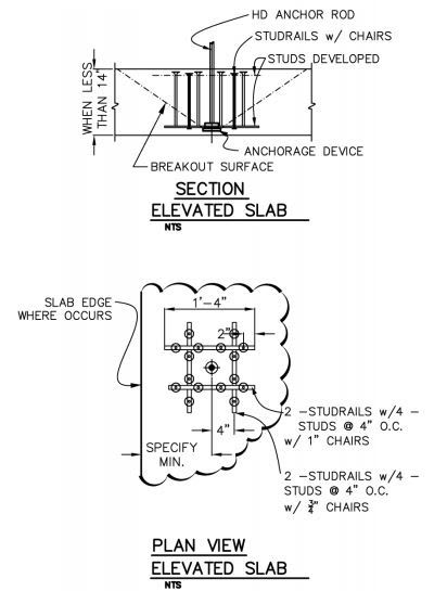
I like something like shown below at a heavier scale if the numbers can be made to work. Maybe stirrups instead of studs at your slab depth and run four anchor rods down to a very thick plate at the bottom. I'd think this would give you better concreting in the area of the connection as well.

C01_wbofmw.jpg
 
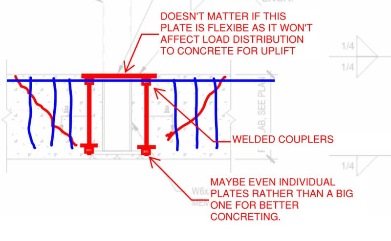
Or something like this taking advantage of:

1) The flexibility of the upper plate doesn't matter much for uplift and would allow you to spread things out legitimately.

2) If you look at the research on regular punching shear, you find that the delivery of load is, in fact, not uniformly spread about the perimeter. Rather, it's localized at the corners of the columns (for squarish ones at least). I think you could lean on that to justify that the use of individual plates at each bolt would still give you the big punching shear capacity. Then you wouldn't have that spalling potential below the plate so much.

As Agent mentioned, this approach starts to cross over into, effectively, anchor design.

C01_mxffop.jpg
 
Status
Not open for further replies.

Part and Inventory Search

Sponsor