Continue to Site

Eng-Tips is the largest engineering community on the Internet

Intelligent Work Forums for Engineering Professionals

  • Congratulations SDETERS on being selected by the Eng-Tips community for having the most helpful posts in the forums last week. Way to Go!

Embedded Pole Constrained/Non-Constrained? 1

Status
Not open for further replies.

RDR89

Structural
Apr 25, 2022
70
Hi all, I have an embedded pole calculation that I am doing per IBC 1807. My question is do you consider asphalt and crushed stone as rigid constraint at the ground surface? There will be 3" of hot mix asphalt on top of 8" of crushed surfacing top course (all this on top of the compacted subgrade). I know that concrete pavement would be considered rigid but I am not sure about this mix. Any insight is appreciated!
 
Replies continue below

Recommended for you

Generally speaking I always consider it non-restrained. Especially in the case of asphalt where on a hot day with substantial wind, the post could likely generate enough lateral force at the ground level to push the asphalt around. Where I practice a hot sunny day can cause asphalt to become somewhat malleable. And it really only gets to 25-30 celcius here.
 
Agree with above - non-constrained.

Even if concrete generally, unless I can actually resolve the forces. That reaction at grade for the constrained calculation can get very large and be difficult to resolve.
 
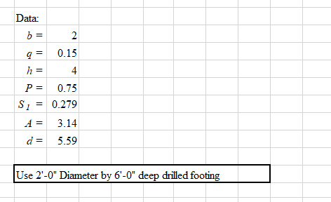
That makes sense. I should have added, the calculation is actually for a very small piece of equipment sitting on top a concrete pedestal that is embedded. I am likening to an embedded post and doing the calculation as such. The pedestal itself is 18"-24" square, but the customer wants it sticking out of the ground ~4', so that is where the majority of the lateral load is coming from. My lateral load at grade level is ~750 lb, so not substantial. That being said, I do agree with you on the asphalt being and becoming more "flexible". I also know that some folks don't consider the top 12" as providing much lateral resistance unless it is concrete. Hence why I posted the question - generally speaking, I don't think it is restrained due to the asphalt, but there is not substantial lateral force. I just don't want to be too conservative where I don't need to be. The IBC formula gives me a required embedment of 4.4 ft restrained but 10.4 ft unrestrained.
 
Also to add, it is a multiple site project in WA state, so high seismic, and I don't have the Geotech reports for any of the sites. I am leaning towards treating it as non-constrained but again, don't want to be overly conservative for the small load. Just trying to get opinions on what might be reasonable.
 
10.4 ft embedment sounds off for a 750 lb load elevated 4 ft off of the ground surface.

Agree with others would consider this unrestrained.
 
Agreed with Celt83, your required embedments sound way off for 750 lb at 4 ft. I'd expect closer to 4'- 4.5' or so for unrestrained depending on values.

You mentioned not having geotech values..What are you using for your allowable lateral bearing pressure? Are you taking advantage of the 2x increase allowed for flagpoles (can the equipment tolerate 1/2in of movement at the ground surface?) Are you increasing the allowable lateral bearing pressure with depth as allowed by the table?
 
OK thanks for the gut check.

Strucbells, I am not taking the increase for the 1/2" movement and I am not increasing the lateral BP with depth as I don't have the geotech reports. I am considering 150 pcf per the Presumptive Load Bearing Values table in IBC.
 
Makes sense why your required embedment is so large. Not taking the 1/2" movement increase is fine based on your understanding of the equipment.

Not increasing the lateral bearing with depth is needlessly conservative in my opinion, it is explicitly allowed by the code for these presumptive (conservative) values. Physically, the soil will be more confined as you get deeper and therefore you get more allowable bearing pressure as you get deeper. As long as you don't have a trench/big grade change/etc. nearby, I don't see a reason to not take this into account. Should fix your issues.
 
Sorry maybe I am misunderstanding... S1 in the IBC formula is the lateral bearing pressure based on 1/3 the depth of embedment... but the required embedment depth changes based on the S1 value used. I used the 150 psf/ft per the table, but how do you determine the required depth if the values change based on the depth?
 
it is an iterative process, when your done the d,calculated by the IBC formula should match the d used to determine S1.

Edit:
My interpretation on S1 is that it is = min(1/3*d*qh, 4*qh) to satisfy the "d shall be not be taken greater than 12 ft for S1 calculation", I've seen others take this to mean that embedment's greater than 12 ft are not permitted by IBC.
 
Gotcha. So if I am reading this correctly... you can increase the lateral resistance by the tabular value for every additional foot of depth and for an unconstrained condition, I am basing the S1 value on 1/3 the embedment. So let's say, as an example, my required embedment is 6 ft in an unconstrained condition and I am assuming a tabular lateral resistance value of 150 psf/ft. 1/3 the embedment would be 6/3 = 2 ft. Therefore my lateral resistance values would be 150 psf/ft for the first "layer" and then (150 + 150=) 300 psf/ft for the second "layer"? Or would it be 150 psf for the first layer and 150 psf for the second layer?
 
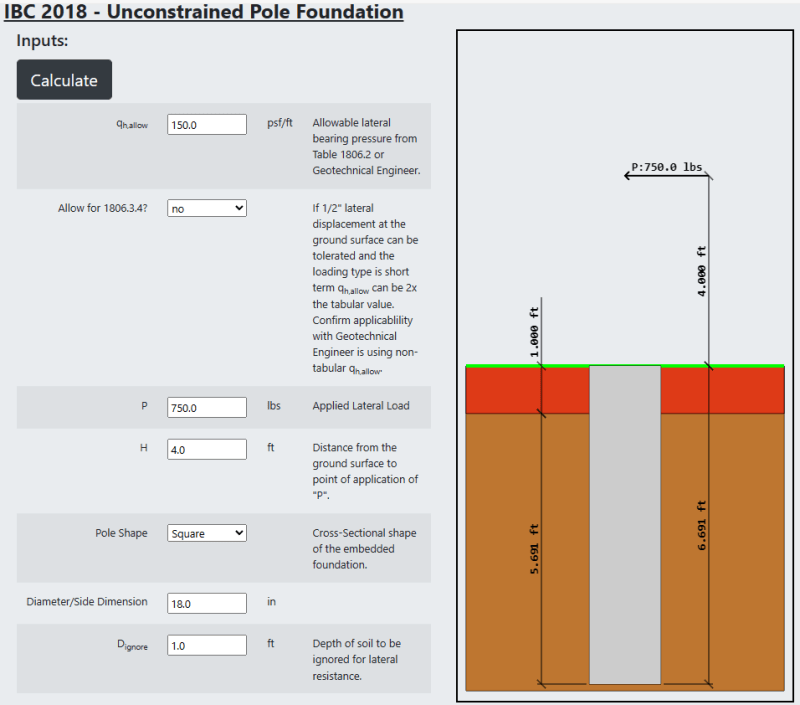
Here's my spreadsheet output for a 2' diameter pier with a 750# load at 4' above grade.

Embed_Output_ezgu8p.png
 
Screenshot_2023-10-18_125517_plzvxn.png


[pre]
Mo : 3750.0000 ft-lbs Effective Moment at the start of embedment.
b : 2.1213 ft Diameter or Diagonal dimension of pier.
S1 : 284.5656 psf Allowable lateral soil-bearing pressure based on a depth of one-third the depth of embedment, however d not over 12 feet for purpose of computing lateral pressure.
A : 2.9073 = 2.34 P /(S1 b)
D : 5.6913 ft Embedment Depth from IBC 2018 - Eq. 18-1
Dtotal : 6.6913 ft Total Embedment = D + Dignore
[/pre]
 
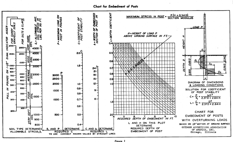
The IBC equation is a modified version of the nomograph developed by P.C. Routledge, if you can find a copy of Pole Building Design by Donald Patterson it provides some additional information:

Screenshot_2023-10-18_143039_vxbqjk.png
 
That is super helpful @Celt83, thank you. Helps me visualize it better. Also, nice website :)
 
I really love nomographs. They're such an elegant way to do things.
 
Is that pole embedment calculation above a website or someone's personal spreadsheet? Celt83?
 
lexpatrie: refer to my eng-tips profile. Feel free to reach out with any questions.
 
Status
Not open for further replies.

Part and Inventory Search

Sponsor