Continue to Site

Eng-Tips is the largest engineering community on the Internet

Intelligent Work Forums for Engineering Professionals

  • Congratulations waross on being selected by the Eng-Tips community for having the most helpful posts in the forums last week. Way to Go!

EN 50522 permissible touch voltage - body resistance question

Status
Not open for further replies.

tofulover

Electrical
Jun 17, 2020
40
Hi all,

I have searched the forum and found a few threads about the permissible touch voltage calculations but the threads do not answer my question so I would like to ask here.

I wanted to calculate the permissible touch voltage as per EN 50522 and/or IEC 60479.

Referring to annexe A of EN 50522, I can see that the permissible touch voltage is calculated using 4 weighted values. I understand that. However, how does one determine the boy resistance in each case?

So if I understand correctly, using a disconnection time of 0.05sec for instance, we need to run 4 calculations and then obtain the weighted values.

Case 1
Ib = 900mA, HF = 1.0, BF = 0.75, Weighted = 1
So U[sub]tp[/sub] = I[sub]b[/sub](t[sub]f[/sub]) x 1/HF x Z[sub]T[/sub](U[sub]T[/sub]) x BF
and weighted value then becomes Utp x 1

Case 2
Ib = 900mA, HF = 1.0, BF = 0.5, Weighted = 1
So U[sub]tp[/sub] = I[sub]b[/sub](t[sub]f[/sub]) x 1/HF x Z[sub]T[/sub](U[sub]T[/sub]) x BF
and weighted value then becomes Utp x 1

Case 3
Ib = 900mA, HF = 0.8, BF = 0.75, Weighted = 1
So U[sub]tp[/sub] = I[sub]b[/sub](t[sub]f[/sub]) x 1/HF x Z[sub]T[/sub](U[sub]T[/sub]) x BF
and weighted value then becomes Utp x 1

Case 4
Ib = 900mA, HF = 0.4, BF = 1.0, Weighted = 0.7
So U[sub]tp[/sub] = I[sub]b[/sub](t[sub]f[/sub]) x 1/HF x Z[sub]T[/sub](U[sub]T[/sub]) x BF
and weighted value then becomes Utp x 0.7

And then get the average value of the calculated Utp from above.

The question is, how do we get the body resistance Z[sub]T[/sub](U[sub]T[/sub]) in the first place?

Thanks for any insight!

Cheers

 
Replies continue below

Recommended for you

Hi Erdep,

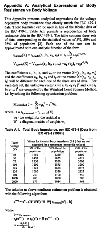
I have herewith an IEEE paper that described more of the analytical equations. However the maths involved is beyond me but you may understand better?

Here is the link:
Link

and here is an extract from the paper above
IEEE_paper_wfexof.png
 
Tofulover

The paper shows how to solve the non-linear circuit graphically.

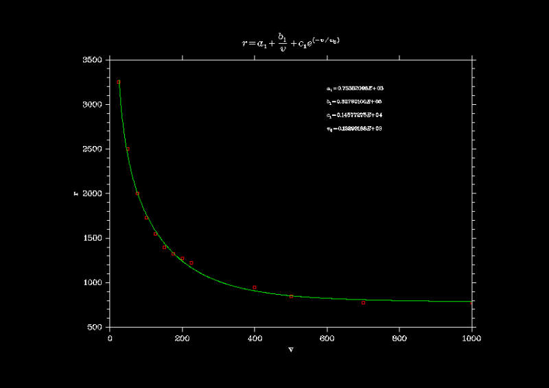
The tables are from a old Standard, I obtained the coefficients for R(V) 50% with the table if EN50522:

There are a lot of linear (as Excel use in your figure) and non-linear fitters.

rdv01_ucu75x.png


[tt] Vtouch Table EN50522 Formula
0.250000E+02 0.325000E+04 0.327324E+04
0.500000E+02 0.250000E+04 0.241037E+04
0.750000E+02 0.200000E+04 0.202020E+04
0.100000E+03 0.172500E+04 0.176875E+04
0.125000E+03 0.155000E+04 0.158538E+04
0.150000E+03 0.140000E+04 0.144407E+04
0.175000E+03 0.132500E+04 0.133198E+04
0.200000E+03 0.127500E+04 0.124157E+04
0.225000E+03 0.122500E+04 0.116784E+04
0.400000E+03 0.950000E+03 0.907718E+03
0.500000E+03 0.850000E+03 0.853298E+03
0.700000E+03 0.775000E+03 0.808193E+03
0.100000E+04 0.775000E+03 0.787399E+03[/tt]

Compare with interpolation method: the table and interpolated agree exactly for all the table values, and interpolation uses simple mathematical operations. It is fast and reliable.

Regards,

OPH. 2020-06-22 05:20
 
Hi Erdep,

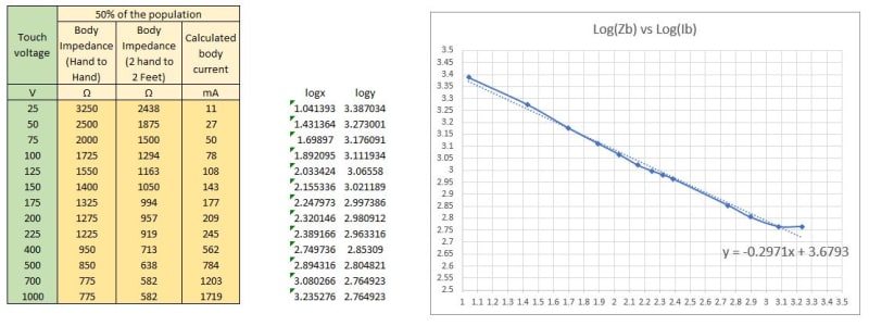
What do you think of my approach using the excel log-log graph method above?

EPR_jgyxbs.jpg
 
Tofulover,

You obtained a table of I(V) and R(I) with exact values for the table values, and a good approximation for the rest of values.

Now, you can use a table of I(t) (or t(I)) to calculate V(t), as the EN50522, with the HF, BF and Weight for each case.

The last step is to compare your values with EN50522 values for V(t)

When RF=0 you can calculate Ib= Vtouch/Rbody= 1000/582 = 1718.2 mA for the last point

When RF > zero the procedure is not so simple but it is solvable by numeric methods.

Regards,
OPH. 2020-06-22 05:48


Thanks Erdep.

I will try now. However, you said "Now, you can use a table of I(t) (or t(I)) to calculate V(t), as the EN50522, with the HF, BF and Weight for each case."

Since the Zbody impedance is already using a BF of 0.75 to give 2 hand to 2 feet, I wonder if the Z(I) table and graph that i should be using should be the original hand to hand value?
 
Hi Erdep,

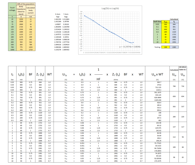
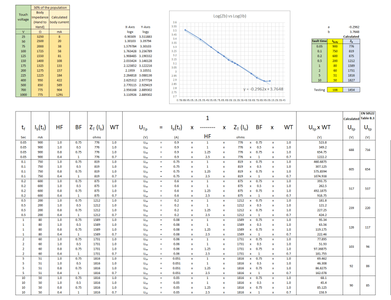
I have now revised the table such that I use the Hand to hand body impedance. The graph is therefore prepared using Log(Zbody(h-h)) vs Log (Ibody). From this graph, I do a linear trend line with the equation as shown.

From the equation, I can then calculate Zbody(h-h) using a value of the body current. This is shown as "calculated Zb".

And using the disconnection time tf as per table B.1, and using the body current from C2 curve, I then apply the BF, HF and WT to the values and obtain an average of the 4 sets of voltages from each disconnection time.

Here is the result:

calculation_nuz51q.png


So from the calculations, the calculated Utp vs Utp from EN50522 Table B.3 is shown as follows:

Calculated Utp vs EN50522 Table B.3
748 vs 716
658 vs 654
563 vs 537
260 vs 220
137 vs 117
112 vs 96
100 vs 86
98 vs 85

What do you think of the above calculations and results?
 
Tofulover,

You calculated the third column of your table (Ibody) applying the BF factor

1000/775= 1290 mA but you have 1719 mA (1290/0.75)

Are you using the third column to calculate Utp?

If yes, you calculate Utp using 1/0.75 times de current.

Regards,

OPH. 2020-06-22 09:53

 
Thanks Erdep. That is a good catch!

Here is an updated version. What do you think.

calculationv2_qluitv.png


The calculated Vtp vs EN 50522 is:

688 vs 716
605 vs 654
517 vs 537
239 vs 220
126 vs 117
103 vs 96
92 vs 86
90 vs 85
 
Tofulover,

A bit better.

The problem with the standard is that the tables are coarse, any deviation from the exact R(V) or I(t) multiply the errors.

If you try with RF > 0 (using the graphic method) the errors are bigger.

It is a case where one must have faith... and I have not faith in the graphics for R >0.

OPH. 2020-06-22 10:54


Thanks Erdep. Good to know I am on the right track.

What I will do next is to bring into the equation the resistance of the ground and see if the calculated touch voltage is similar to your calculation.
 
Hi Erdep,

I have now tried in the past few days to obtain the permissible touch voltage taking into consideration of the resistance of the footwear and the ground but I am not getting the results I enticipated.

Could you please have a look below and see if I am doing this correctly?

Assuming soil resistivity (p1) of 200ohm-m and the resistivity of the surface material (p2) is 500 ohm-m with a depth of 0.18m.

U[sub]tp[/sub] = I[sub]b[/sub](t[sub]f[/sub]) x 1/H[sub]F[/sub] x [ (Z[sub]T[/sub](U[sub]T[/sub]) x BF) + R[sub]F1[/sub] + R[sub]F2[/sub] ] x WT

RF1 = resistance of footwear = 1.5 x effective resistivity of soil (say 200 ohm-m) = 1.5 x 200 = 300 ohm

Calculate RF2, first calculate reflection factor, K.

K = (p1 - p2)/(p1+p2) = -0.428
C as per IEEE Std-80 equation 27 = 0.88
RF2 = 1.5 x Cs x surface resistivity = 1.5 x 0.88 x 500ohm-m = 660 ohms

Could you please advise if my calculation methodology above is correct in the first place?

Thanks!
Tofu

 
Hi Erdep,

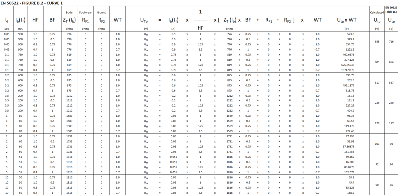
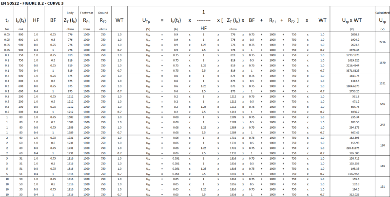
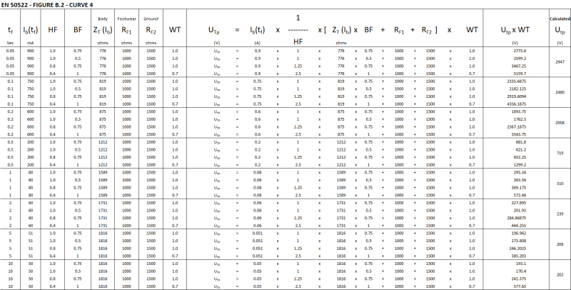
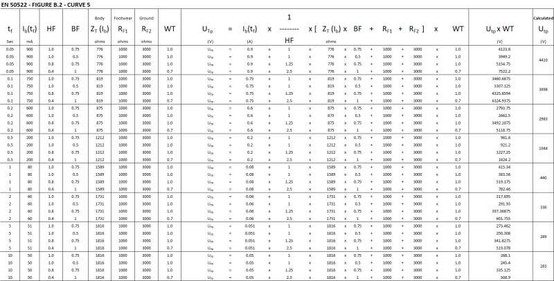
I have now carry out more investigation. I think the way EN 50522 calculated the permissible touch voltage when RFI and RF2 are > 0 is to ignore the weighted value obtained using HF=0.4, BF-1.

So with this hypothesis in mind, I then calculated a series of Utp based on the RF1 and RF2 values of Figure B2 of EN 50522.

So let me present this in the screenshots below:

1_-_IYGvLVq_celblc.png


2_-_UZjyw2Q_vbl004.png


3_-_d7yurx0_lpvhba.png


4_-_icdVevW_bm9qus.png


5_-_tbLcQWB_dtz4ge.png


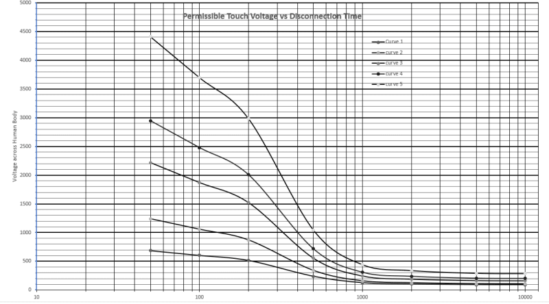
and when I plot all the curves 1 to 5, this is what I get.

1_-_mqNj6dZ_tpvi4k.png


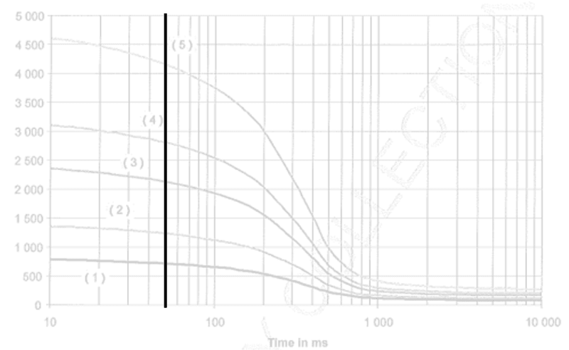
and drawing reference from Figure B2 of EN50522, I have changed the screenshot to have a more transparent background for comparison purposes

2_-_uTUNNx2_my0l4l.png


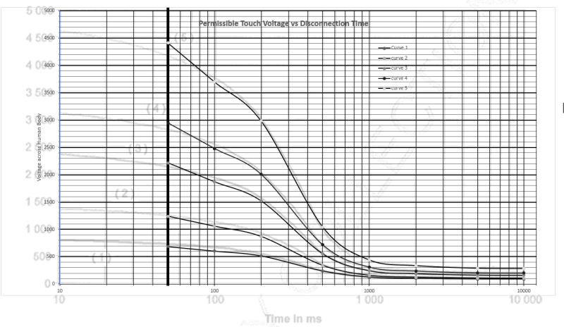
and if I overlay the excel graphs obtained on top of the EN50522 curves, this is what I get

3_-_MTPBnE1_tcgmsl.png


My observations:

1. The Utp values at 50ms is quite close for curve 1 to 3, but started to deviate for curve 4 and 5
2. The rest of the curves roughly follow the same profile as EN50522

What do you think? Would like to see your comments please.

Thanks
Tofu
 
Hi Tofu

I have also asked the same question in this thread:
I also asked how to calculate Utp value at 0.05 s. I got the following reply from Erdep:

TIME OF FAULT : 0.05
HF : 1.
BF : 0.75
WEIGTH : 1.
TOTAL ADDITIONAL RESISTANCE : 0.
BODY RESISTANCE : 820.939836 at 554.13439 V
CORRECTED BODY RESISTANCE : 615.704877
TOTAL TOUCH RESISTANCE : 615.704877
PERMISIBLE BODY CURRENT : 900.
PERMISIBLE TOUCH CURRENT : 900.
BODY VOLTAGE : 554.13439
PROSPECTIVE TOUCH VOLTAGE : 554.13439

TIME OF FAULT : 0.05
HF : 0.8
BF : 0.75
WEIGTH : 1.
TOTAL ADDITIONAL RESISTANCE : 0.
BODY RESISTANCE : 780.306292 at 658.383434 V
CORRECTED BODY RESISTANCE : 585.229719
TOTAL TOUCH RESISTANCE : 585.229719
PERMISIBLE BODY CURRENT : 900.
PERMISIBLE TOUCH CURRENT : 1125.
BODY VOLTAGE : 658.383434
PROSPECTIVE TOUCH VOLTAGE : 658.383434

TIME OF FAULT : 0.05
HF : 1.
BF : 0.5
WEIGTH : 1.
TOTAL ADDITIONAL RESISTANCE : 0.
BODY RESISTANCE : 929.401269 at 418.230571 V
CORRECTED BODY RESISTANCE : 464.700634
TOTAL TOUCH RESISTANCE : 464.700634
PERMISIBLE BODY CURRENT : 900.
PERMISIBLE TOUCH CURRENT : 900.
BODY VOLTAGE : 418.230571
PROSPECTIVE TOUCH VOLTAGE : 418.230571

TIME OF FAULT : 0.05
HF : 0.4
BF : 1.
WEIGTH : 0.7
TOTAL ADDITIONAL RESISTANCE : 0.
BODY RESISTANCE : 775. at 1743.75 V
CORRECTED BODY RESISTANCE : 775.
TOTAL TOUCH RESISTANCE : 775.
PERMISIBLE BODY CURRENT : 900.
PERMISIBLE TOUCH CURRENT : 2250.
BODY VOLTAGE : 1743.75
PROSPECTIVE TOUCH VOLTAGE : 1743.75

To calculate Utp at 0.05s, (554.13+658.38+418.23+1743.75*0.7)/4= 713 V VS 716 V according to EN standard table B.3.

What I didn't understand is how the body resistances are calculated in the info above i.e.:

BODY RESISTANCE : 820.939836 at 554.13439 V
BODY RESISTANCE : 780.306292 at 658.383434 V
BODY RESISTANCE : 929.401269 at 418.230571 V
BODY RESISTANCE : 775. at 1743.75 V

I gave up, but seeing you excellent work, I think you are close figuring out how to derive the UTP curves.

Further values recieved from Erdep below:

NR. Tf (S) UvtP I Table B.1 Table B.3
----========------------============
1 0.05 712.8433 900.0000 716.0000
2 0.10 610.6242 750.0000 654.0000
3 0.20 508.3179 600.0000 537.0000
4 0.50 219.5357 200.0000 220.0000
5 1.00 116.7734 80.0000 117.0000
6 2.00 95.6989 60.0000 96.0000
7 5.00 85.4868 51.0000 86.0000
8 10.00 84.3328 50.0000 85.0000
 
Status
Not open for further replies.

Part and Inventory Search

Sponsor