Continue to Site

Eng-Tips is the largest engineering community on the Internet

Intelligent Work Forums for Engineering Professionals

  • Congratulations waross on being selected by the Eng-Tips community for having the most helpful posts in the forums last week. Way to Go!

Encased Steel Beam in Concrete 4

Status
Not open for further replies.

bulbamon

Structural
Sep 12, 2022
9
Hello. I want to ask about the theory of encased steel beam in concrete. I have an I wide flange steel (dimension 588x300x12x20) encased in a concrete beam (600x950mm). I have a screenshot of the section below.
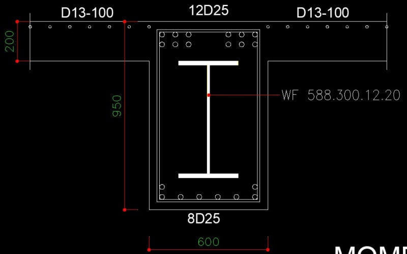
Screenshot_2022-09-12_230557_vjf4ne.jpg


If I want calculate the moment capacity:

1. Do I have to consider the principals of LRFD design of reinforced concrete which are : the compression strain limit of the concrete beam is 0.003, check if the steel has yielded (to make sure the beam is under-reinforced), and if the portion of web or flange is not yet yield I have to use the fs (stress corresponding to the strain)...?

2. Or, do I assume it is designed like a typical composite beam with concrete slab, which is the steel section calculated using plastic stress distribution?

I am leaning towards the first option because it is like an usual reinforced concrete beam with rebar, but what makes me confused is that the steel section will not achieve the maximum capacity because we limit the strength by the strain distribution diagram, whereas if there is no concrete encasement, the steel profile alone can achieve plastic stress distribution...and, there is still an issue with over-reinforcing the concrete beam.

But if I choose the second option, what will happened to the concrete if I ignored it during my design. Will it have a large crack first, so that the steel beam can act freely to achieve the plastic moment capacity..?

I will appreciate your thoughts about this. Thank you for all your help.
 
Replies continue below

Recommended for you

Unless you provide shear studs or some form of credible connection between the steel and the concrete, I would say this is a steel beam.
I don't know the specifics, but if this is a beam it looks unbuildable to me.
The bottom flange will stop any attempt of concreting and proper compaction between the bottom rebar.
 
It's been some time but, when last I checked, AISC allowed one to treat an encased steel beam as a fully composite beam. That, even with no studs at all. I initially found that surprising but my work in other spaces, such as piling and shear friction, leads me to believe that steel to concrete bond is often much more effective than we typically give it credit for. At the least, that's the case for static, monotonic loading.

I believe that the beam is in fact buildable at the proportions shown. Very similar things are done with high rise shear wall coupling beams with some regularity. Some consideration should be given to the appropriate mix design of course.

I don't feel that it's appropriate to follow your path #1 and, effectively, treat the steel beam like nothing more than additional rebar. Rebar is assumed to posses negligible flexural stiffness whereas your steel beam will possess very significant flexural stiffness. That difference, and all that it implies, neuter that approach in my mind.

I wouldn't sweat tension side crack control. You should be able to provide enough bonded reinforcement in the bottom of the beam to be able to keep that under control if the bond with the beam fails in that regard.

 
Thank you kostast88.

I am thinking about using self compacting ooncrete for this beam. Maybe it can help with the bottom flange blocking the concrete problem.

If I treat this as a steel beam only, is it safe for the concrete? Because the owner insists that they want to cover the steel beam with concrete. And I don't want the concrete that encase the steel beam to crack too wide either.

 
Thank you KootK for your thoughts on this thread. They are very helpful.

Yes, for the inertia and stiffness it is better to follow #2 path.

But what confuses me is the strain distribution because now concrete got involved (the ratio of reinforcement limit and the concrete crushing limit at strain 0.003).

Do we need to consider those? And if those things are needed to consider, then are we still allowed to use plastic stress distribution for the steel profile? (calculating the strength using Fy of the steel).

 
In my mind, the first question is whether there is sufficient bond to get full shear transfer between the concrete and the steel beam (assuming there are not shear connectors of some kind that provide adequate shear transfer capacity). Without establishing that, which I don't know how you could, I wouldn't assume composite action, if it were me.

If you ignore composite action, the problem becomes fairly straightforward, other than the requisite strain compatibility analysis to determine the strain, and thereby the stress, in the steel beam at failure of the concrete (based on whatever strength or serviceability criteria constitutes failure in this instance) or yielding of the reinforcing steel. To be conservative, I would include the steel beam in the check for the strain limit of the concrete (since you may get some composite action, even if you don't consider it reliable enough to consider in the capacity calculations) Once you have the max stress allowed for the steel beam, that will give you the usable capacity of the steel beam, which I would add to the capacity of the reinforced concrete beam, as if they were beside one another.

Rod Smith, P.E., The artist formerly known as HotRod10
 
You appear to have the room for additional reinforcing. Why is it necessary to include the the steel beam at all, rather than designing and constructing a standard reinforced concrete T beam?

Rod Smith, P.E., The artist formerly known as HotRod10
 
Thank you BridgeSmith for your thoughts on this thread.

If i want to use the method that you suggested (designing WF beam alone, concrete beam alone, and then add them to get the moment capacity). Will it be considered as a fully composite beam with full composite action? And about the reinforcement limit (As Max), do I still need to consider that? Because the area of total rebar + WF beam will exceed the As Max for the concrete dimension.

Yes I still have room for reinforced concrete rebar, but the owners want to use encased beam instead.


I think you can consider this as composite. But the last time AISC mentioned something like this in code was (IIRC) in the 1990's with the second edition of the LRFD manual (i.e. the silver book).

Another good source could be: 'Composite Construction Design For Buildings' by: Viest, et al. (1997; published by: McGraw-Hill/ASCE).

 
OP said:
Do we need to consider those? And if those things are needed to consider, then are we still allowed to use plastic stress distribution for the steel profile? (calculating the strength using Fy of the steel).

I believe that you would consider strain by following pretty much the same deign procedure that you would have were this a flat slab poured over a steel beam and fully shear connected. That procedure pays homage to strain.
 
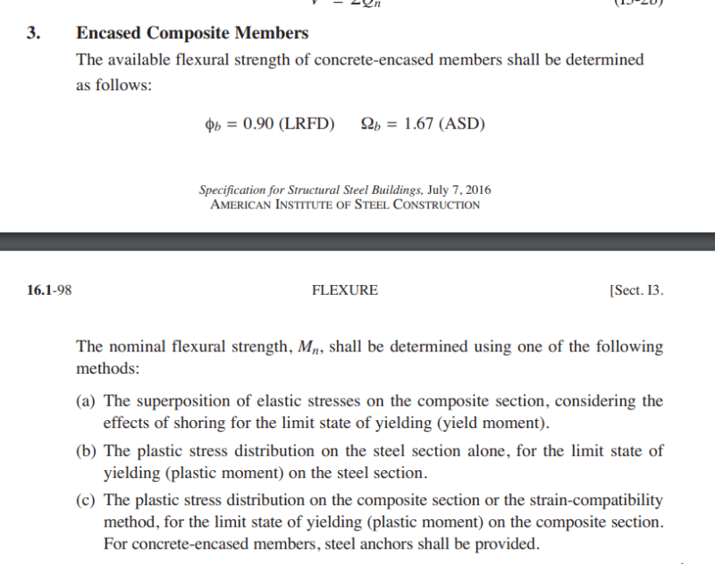
This is what the current edition of AISC 360 has to say about encased, composite beams.

C01_f5y7t8.png
 
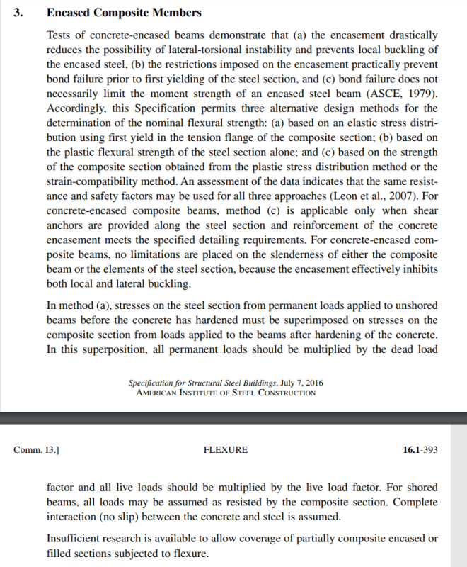
And the commentary which speaks more explicitly to the shear bond issue. It appears that shear connectors would be required for the conventional methods of composite design. without those, it's down to steel only or a composite design limited to first yield of the steel.

C01_fu7wl9.png
 
If i want to use the method that you suggested (designing WF beam alone, concrete beam alone, and then add them to get the moment capacity). Will it be considered as a fully composite beam with full composite action?

That would be the approach considering it as non-composite; basically as 2 separate beams.

And about the reinforcement limit (As Max), do I still need to consider that?

The As Max is a limit to prevent an overreinforced section that could have a brittle failure. I believe that would be precluded by limiting the strain and stress in the steel beam so that the strain in the concrete is below the crushing limit.

Rod Smith, P.E., The artist formerly known as HotRod10
 
Hi all. I am very sorry for the late reply.

Thank you WARose, KootK, and BridgeSmith for all your help and thank you for all the discussion on this thread.

 
Hello.

An update on my design, I am thinking of following what AISC 360 said in Chapter I3 option (c) about Encased Composite Members, that is, by using plastic stress distribution or the strain compatibility with shear studs provided on the steel beam.

I am currently making a strain diagram for the concrete and steel beam so the stress distribution that happens in the steel beam match with the strain compatibility. The strain limit for concrete is 0.003, the yield strain for the rebar is 0.002 and the yield strain for the steel WF beam is 0.0012 (I assume the WF beam has a yield stress 240 MPa).

What I want to discuss are :
1. I calculate concrete beam using T concrete beam theory, and because of that, the N.A. (neutral axis) is in the concrete slab. So the WF beam will be in full tension. But based on the strain diagram, for the upper flange and small portion of the upper web is not yielded yet (< 240 MPa) because the strain is still 0.0006 for the upper flange and 0.0008 for the upper web, so the stresses are 129 and 164 MPa (red mark on the picture). Is this the correct procedure in order to calculate the moment capacity of the composite beam?

2. For the compression region (above N.A), I provide shear studs so the strain will remain linear and not slip between the steel beam and the concrete. But for the tension region, does it still need studs to make sure the tension force from rebar and tension force from the portion of the WF beam can work together?

I appreciate your thoughts about this matter. Thank you for all your help.
Capture_nvrxd4.jpg
 
That looks like the correct procedure for the ultimate capacity of the composite beam using strain compatibility.

I haven't delved deeply enough into the mechanics and research to say with any confidence that it would behave as fully composite without shear studs. If it were me, I'd design the shear studs for ultimate capacity and fatigue (if applicable), and have them shoot them on.

Rod Smith, P.E., The artist formerly known as HotRod10
 
Status
Not open for further replies.

Part and Inventory Search

Sponsor