Eng-Tips is the largest engineering community on the Internet

Intelligent Work Forums for Engineering Professionals

  • Congratulations waross on being selected by the Tek-Tips community for having the most helpful posts in the forums last week. Way to Go!

End face as secondary datum feature for runout - redundant?

Status
Not open for further replies.

Burunduk

Mechanical
May 2, 2019
2,335
0
0
IL
In runout examples 7-61, 7-63, and 12-2 of Y14.5-2018, the primary datum feature establishes the axis of rotation and constrains 4 degrees of freedom, thus stopping the relevant rotations and translations to allow the tolerance zone limit the feature. The secondary datum feature is an end face, not applying any rotational constraints to the part relative to the datum reference frame. The translational constraint applied by the end face has no relevance, since runout doesn't control location in the axial direction. Then what value does the secondary reference add?
Of the three figures, I can only see how it contributes in defining the limited area for check on the cylindrical feature in 12-2, but not useful for the cone control.

BTW, speaking of 12-2 is it just me or there are multiple errors with how the tolerance zones and limited variations are shown?
 
Replies continue below

Recommended for you

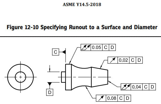
The example posted by greenimi is almost same as the Figure 12-10 (2018), when the cylindrical feature is too short to locate the part, the surface will act as primary to orient the part first, then the cylindrical feature locates the part in the assembly.

In this case, the surface will be the primary datum feature and the cylindrical will be the secondary datum feature.

2023-06-06_070148_fmtf2d.jpg


Season
 
Belanger said:
greenimi -- that example has the surface feature as the primary datum, so it makes sense. The OP question was about the value of having the surface datum be secondary (where it might not seem to add any value to the runout idea).

I agree with your assessment and to the fact that having the surface datum as a secondary in the runout example might not be a value added approach. Maybe, as Burunduk alluded to, having an extra explanation/note to clarify the intent is a good idea. (Note such as "DATUM FEATURE B (or whatever letter) IS INVOKED TO CONSTRAIN AN ADDITIONAL TRANSLATIONAL DEGREE OF FREEDOM OF THE DATUM REFERENCE FRAME").

Again, I am considering the same line of thinking as figure 9-4/ 2018 (in the Means this section)
 
But still... in Fig. 9-4, the secondary datum (or lack of secondary datum) might change the resulting measurement of the geometric tolerance.
With the OP question, the secondary datum (or lack of secondary datum) won't have any effect on the resulting measurement.

John-Paul Belanger
Certified Sr. GD&T Professional
Geometric Learning Systems
 
In the original question, it does affect the result because otherwise other portions of the surfaces or no surfaces at all for the primary datum feature will be in contact with the targets.
 
I'll admit that I didn't look at the graphics -- I just read the question quickly. Yes, Dave, the secondary datum does set up the basic dims for the datum targets (or the gaging area for Fig. 12-2).
My bad :)

John-Paul Belanger
Certified Sr. GD&T Professional
Geometric Learning Systems
 
greenimi,
Thanks for the Y14.47 reference, I didn't know about it.

I wonder, why is there a need for another ASME standard on MBD when Y14.41 Digital Product Definition Data Practices is available?
 
On the one hand, standards are created and essentially paid for by people who benefit, typically for marketing purposes.

On the other it covers aspects of MBE that Y14.45 doesn't.

For my interests, if it doesn't define a model for a seamless round trip through all major packages with no difference except the time stamp, then the case for MBE standards governing that is weak.

It outlines model organization schema practices to support model-based definition (MBD), and provides a set of requirements and guidelines for the computer-aided design (CAD) user.
from
See also
So - it appears, in part, to tell the CAD user what to do. I cannot imagine the disappointment users of certain CAD systems would have at following good modeling practice guidance. (Those who know, know.)

It was published just this year. How funny - it was first published in 2019, then "updated" in 2023, but the linked table of contents is to the 2019 version. Way to go ASME.

I would love to see the committee roster for this, but not $68 worth of love. Nearly $2 a page is too much.

---

And here it is:

In late 2018 and early 2019, Revision B of MIL-STD-31000 and the first edition ASME Y14.47-2019 were published – completing the transition of Appendix B to a national standard and removing Appendix B from MIL-STD-31000.

IOW, move it from the available-for-free MIL-STD-31000 to the make-them-pay-dearly ASME standard.

 
Status
Not open for further replies.
Back
Top