Continue to Site

Eng-Tips is the largest engineering community on the Internet

Intelligent Work Forums for Engineering Professionals

  • Congratulations KootK on being selected by the Eng-Tips community for having the most helpful posts in the forums last week. Way to Go!

End release of hanger column

Status
Not open for further replies.

Samuee

Structural
May 11, 2018
20
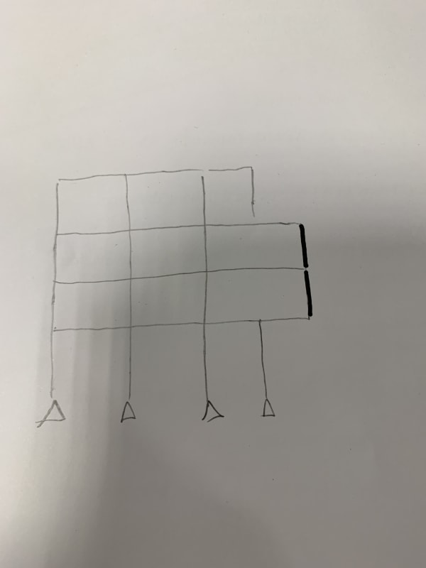
As shown in the attachment, I found the highlighted column is having a large bending moment due to the moment from transfer beam, at the same time it is a cantilever object. Is it a logician assumption if I assume both end of the column is released in moment (There will be increase in moment at beam but it’s ok for my case)

Thanks buddy
image_owj0jc.jpg
 
Replies continue below

Recommended for you

1. How do you WANT the column to act? I.e. what is your “design intent”?

2. How do you plan to connect the beam to the column?
 
OP said:
Is it a logician assumption if I assume both end of the column is released in moment (There will be increase in moment at beam but it’s ok for my case)

Yes, that's a fairly common assumtion to make and it's fine to do so so long as your detailing and design matches your assumption. Use of a standard clip angle shear connection (wide flange column) or a single plate shear tab (HSS column) at the top would normally be deemed sufficient to accomplish this. So would a bolted base plate at the bottom so long as your transfer beams are designed to be sufficiently stiff. The fact that your coming up with appreciable moments in the column may be an indication that your transfer beams are, in fact, not sufficiently stiff.
 
Sorry I need to supplement that this is a reinforced concreted structure

Dear JLNJ,
The structure in my model is mainly resisted by shear wall under wind load. Therefore this column has little contribution in lateral stability. It mainly support the gravity load of cantilever portion at this structure. If I model it as rigid joint, the whole part act as somehow like portal frame in vertical direction to support the cantilever portion load. If I model it as pin support, the cantilever load mainly act on the three beam directly. However, the column size is restrained in my case while beam size is capable of taking the moment even column is pinned

Dear KootK,
I plan to design the beam column connection as rc moment connection with sufficient anchorage as In reality, the column will experience certain degree of bending. However, I make sure that the transfer beam is well designed such that it provide sufficient bending capacity by assuming column is pinned in the model. Is there any concern for my assumption.

My major concern is, the beam column connection is moment joint for rc detailing, the column is continuous all along the two floors. Even though, can I assume it as a pin joint? My thought is, I indeed conservatively treated this joint, and conservatively designed the beam under this assumption. Like people commonly model column base detailing into foundation as pin joint, indeed they use full anchorage reinforcement in detailing

Thanks all for addressing my concern
 
In concrete, my first choice would be this:

1) Design the column and the joint assuming the joint to be flexurally rigid.

2) Design the transfer beam assuming the joint to be flexurally pinned.

The classic, bracketed engineering solution.

Some other options that I like less:

3) Use goofy joint detailing to try to emulate a physical pin. I have little confidence in this.

4) If your columns see axial tension, try to estimate the extent of tensile cracking and use that to reduce flexural stiffness.

As I mentioned previously, a stiff transfer beam is your friend here. The stiffer the beam is, the less moment the column will see.


I wouldn't pin the columns, as it will make the design of beams unnecessarily difficult. Fix the joints as usual, but allow moment redistribution manually.
 
Status
Not open for further replies.

Part and Inventory Search

Sponsor