Eng-Tips is the largest engineering community on the Internet

Intelligent Work Forums for Engineering Professionals

Energy density of a 7-10.5 kW instant electric shower heating element 4

Status
Not open for further replies.

Jack Benson

Industrial
Jul 11, 2023
101
0
0
SK
Hello,

in the UK, Ireland and several other EU countries, instant electric showers that heat cold water at the point of use are common.

in the shower unit is a heating element that is between 7 to 10.5 kW (230v 30-45 amps)

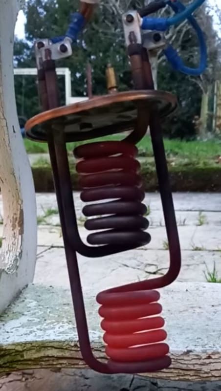
Normally a coil heating element is used like this:

heating_element_coil_rglgxx.jpg


does anyone know the typical energy density (W / cm2) of the heating element?

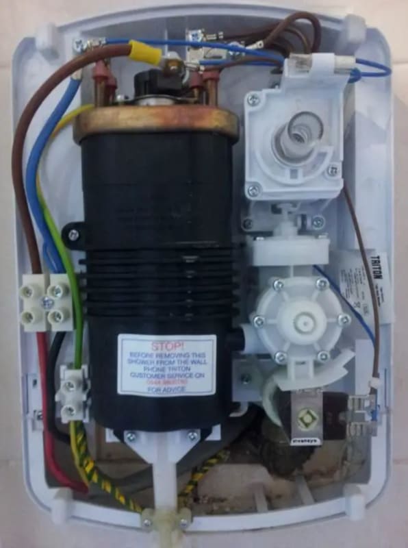
inside_instant_electric_shower_hn1bli.jpg


thank-you
 
Replies continue below

Recommended for you

You have turbulent flow - there aren't any calculations to solve your problem. You can calculate how much heat is required to raise the average temperature at some given flow rate, but the detailed interaction needed for what seems to be quest for the exact and only possible maximum perfect answer to get to some exact, but not lime depositing condition in the exactly smallest volume is not quantifiable.

The factors you have are not sufficient. Even in non-turbulent flow, the shape affects flow.

Put thermocouples into the heating element and use a feedback control to ensure the heater temp is never too high regardless of input water temperature.
 
A 3.5 kW shower would be a dribble if fed with cold water.

Where is 40C water coming from, which is all you need for a shower. This isn't making sense.

An 3.5 kW instant water heater is for washing hands.

Remember - More details = better answers
Also: If you get a response it's polite to respond to it.
 
3DDave is going the same route I was thinking. The overall kw rating or heat flux of the element in this configuration is going to be difficult to calculate. Consider, you want the most surface area possible since your surface temperature is limited to 60-65C. You may need a much higher max wattage element and as suggested use a thermocouple-controlled loop to keep the surface temperature within tolerance. This may be a trial-and-error sort of testing to get things worked out.
 
The system has a heat exchanger in that recovers heat from use shower water. The preheated Coldwater can reach 35C.

There is a preheat mode in the system where we recirculate water Using a pump past the heating element to heat the inner workings of the system. In this scenario the inlet temperature can reach for 40c
 
Seems like a very complex system for a 5 minute shower....

But limescale is really a chemical issue.

Or try one of those electronic things which claim to reduce limescale.

Warm water coming in may increase deposition.

Remember - More details = better answers
Also: If you get a response it's polite to respond to it.
 
our current heating element which is 27W/cm2 (3600W/135cm2=27W/cm2
The picture looks like two heating elements. Are they in series or parallel? Are the numbers you provide for one or both?

this design we get to 8w/cm2 ( 3.14*10*1360mm = 427.04cm². 3.5 kW / 427 = 8.19)
Same question, are there going to be two of these or are you trying to do the work of the two in the first picture using just one element?

 
As for 3DDave's comment, that's why you give yourself some overhead. In your favor water has very high thermal conductivity. If you can regulate your heater current so that the outlet temperature is max 48C you still have nearly 30°C of fudge room before scale formation starts. Consider sizing your heater so that it has 30% excess capacity (standard assumptions for HX design) and use a temperature controller to turn it down the rest of the way.
 
Google tells me safety requirements are for a max hot water temp of 50degC to prevent scalding for domestic instant water heaters. With a max permissible heating surface temp of 75degC to avoid or minimise surface scale,

Q = UA dt, Q/A = U. dt, where Q/A = w/m2 of heat transfer per m2 of heating element surface area

Table 11-2 in Perry Chem Engg Handbook states a U value of 70btu/hr/ft2/degF = 400w/m2/degK for agitated heat transfer to coils immersed in water for condensing steam in the coils. Using this

Q/A = 400x(75-50) = 10 000 w/m2 = 6.45w/in2 heating density = 1w/cm2 at the hot end, and it is slightly more at the cold end with water feed at 40degC.

Use longitudinal fintube elements to get more surface area. Am not having any luck finding a supplier for these at the moment on the net - most of them are transverse fintube, which may probably be impossible to clean in case they do scale up.
 
OP,
I'm glad georgeverghese brought Q = UA dtlog into this thread, because at the end of the day, this is going to be the controlling statement/equation. The wildcard here in my mind is a solid value for U. I am not sure of your background in thermo but you seem to know some. "U" - overall heat transfer coefficient is 1/U=1/h1=+L/lamda+1/h2
where: h = convective heat transfer coefficient, W/(m2°C) [Btu/(hr-ft2°F)], L = thickness of the wall, m [ft], λ = thermal conductivity, W/(m°C) [Btu/(hr-ft°F)]. The "U" variable describes the heat movement from the heating element, though its sheath and into the water.
400w/m2/degK for agitated heat transfer to coils immersed in water for condensing steam in the coils.
My initial gut reaction was this was not accurate because the driver of latent heat transfer does not exist in this scenario but the more I thought about it, an argument could be made for a higher and lower U value in my mind. I will do some more digging or maybe someone more versed in this application will pop on and clear things up. At any rate, I think the "U" value may fall somewhere between 300 and 500, so 400 may be appropriate for a back of a napkin calculation.
My back of napkin calc took a different approach of the required cooling rate to keep the element below 65 C based on a flow rate of 6 lpm and delta T of 25 deg. I came up with 20w/cm^2 as the max surface flux allowed to not exceed 65C. This is assuming a huge number of things and should NOT be used for design purposes. I am only bringing it up to say that your design of 8W/cm^2 seems reasonable. I could see some fairly easy ways of testing this, but I would need to know more information about your original design (see previous questions).
 
sorry - i thought i replied but i must have hit preview instead of post

Heaviside1925 said:
The picture looks like two heating elements. Are they in series or parallel? Are the numbers you provide for one or both?
they are in parallel. Total surface area across both elements where heat is emitted is 135 cm2 with total power output of 3600W

Heaviside1925 said:
Same question, are there going to be two of these or are you trying to do the work of the two in the first picture using just one element?
This will most likely be a single coil with a surface area of 427 cm2 and a power output of 3500W

can you share your back of the napkin calculations? i would very much appreciate it
 
The current design example photo looks like the result of a positive feedback loop. The energy output along the length of the heater is a constant, but to accomplish that as the water entering at one end heats, the temperature increases to emit energy that energy along the heater. The hotter the water gets the hotter the heating element gets.

In the current design example photo does the water enter along the centerline?

As the temp increases in the flow direction the power into the heater needs to decrease at each incremental location in order to limit the temperature gain.
 
3DDave said:
In the original example photo does the water enter along the centerline?

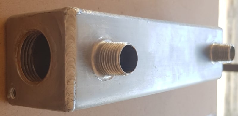
the 1" threaded hole on the side is where the heating element attaches

the inlet is to the left and the outlet is to the right

Water_Heating_Chamber_s7m44u.jpg
 
This is a teardown of a shower unit -
Note that the two heating elements are separately operated and provide different amounts of power, with the lower power element closer to the outlet. Also note that the water inlet is not axial and there is a counter-flow aspect to the outlet tube to help average the heat transfer.
 
Ok - then depending on how the element is installed the current design elements could have their flow restricted against the walls of the housing causing that taper to the lime buildup.
 
3DDave said:
Ok - then depending on how the element is installed the current design elements could have their flow restricted against the walls of the housing causing that taper to the lime buildup.
can you explain in simpler terms?
 
can you share your back of the napkin calculations? i would very much appreciate it
I do not typically do that unless it's a very simple case. I will point where I am looking.
Consider the enthalpy of water, i.e. heat content per mass. You can look them up here: With a flow rate you are moving heat out of the system, and you are putting heat into with your heating element. Consider the different enthalpies of water at 40, 50 and 65 C. From that you can determine the amount of heat in each state. Convert volumetric flow to mass flow and you now have a relationship between rate of heat entering the system vs heat leaving the system. You also have a relationship Q = UA dtlog of the rate at which the heat moves from the element into the water. Consider with water, at low pressures and temps, it's very easy just to move a decimal place to go from cm to m and m^3 to kg. This is how I arrived at the number I provided. BUT there are considerations around flow velocity and how the fluid stream interacts with the surface of the element that I do not know and could have a sizable effect on the final number.
A test you could run, monitor your existing element surface temp at the max flow rate of 6 lpm with 40 deg inlet water. If exceeds 65 deg C increase flow until you have a flow rate that keeps the surface temp below 65C. Now you have relationship between W/cm^2 and flow rate, where you can calculate the max W/cm^2 at 6 lpm. You may even find that 6 lmp exceeds the flow required, which would mean there are transient states, such as low flow and such, where the elements' surface temp is exceeding 65C, in which case, there would need to be additional controls to keep the surface temp from exceeding 65C.
 
Because the water remained colder to the inside it delayed limescale formation; where it was impeded on the outside the limescale formed closer to the inlet.

Picture if the heating element was tight against the wall; very little flow would happen and the water would be much hotter than if it was in free-flowing conditions. Of course the hotter the water, the less heat transfer from the element, which means the element gets hotter yet, spiralling up to a higher temperature. The temperature gradient results in a lime scale deposition gradient.
 
georgeverghese said:
Talk to tech reps at companies like Wattco or Chromalox also to give you values of U with your limitations.

i do not think its that simple, because the design of the heating chamber will affect the flow rate m/s of water over the heating element which will massively effect the heat transfer and therefore the peak temp on the heating element

i did not consider that the water is actually moving very slowly in the heating chamber because it goes from a circular pipe with a cross sectional area of 78,54 mm2 to a Cuboid with a cross sectional area 2916 mm2 (less the cross section of the heating element).

the speed of water in the heating chamber will be very low.

i will need to both increase the surface area of the heating element and decrease the area of the heating chamber - but i need to be careful that i do not add new problems by doing so
 
Status
Not open for further replies.
Back
Top