Eng-Tips is the largest engineering community on the Internet

Intelligent Work Forums for Engineering Professionals

  • Congratulations waross on being selected by the Tek-Tips community for having the most helpful posts in the forums last week. Way to Go!

Equal pipe length 2

Status
Not open for further replies.

Globy

Automotive
May 18, 2014
7
0
0
PT
Hello, people

How can I make equal length pipes? I tried equations but unsuccessfully.

I tried with splines, and smart dimension the splines, but then if you change the position of the point, don't know why the total measure is not the same.


Untitled_nd0txz.jpg


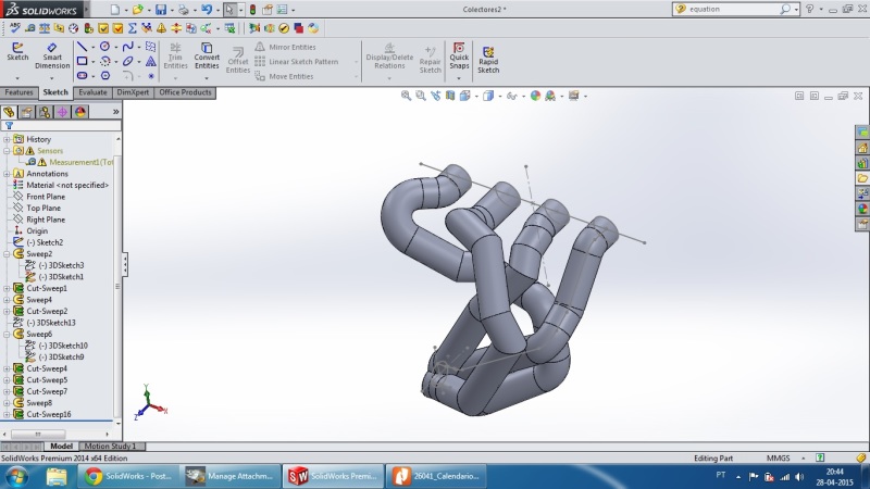
It is attached the file.


Regards
David

 
Replies continue below

Recommended for you

I think you need to convert your sweep/cut paths into splines. But first I would suggest creating a global variable called "spline length" or something. Set this variable to your desired runner length. Then you can edit the splines and attached a length dimension to it. Set this length on each sweep/cut path to this gobal variable "spline length". Now all the paths will remain the same lnegth and you drag your spline segements around to make the runners nest nicely while being assured that that your runner length will always be the same. You will want to play with the spline end tangencies to make sure that the spline always exits the end of the runners perpendicular to the diamter of the runners.
 
I should have added make sure the start and end of your splines are constrained in location and tangency so that the end will always stay perpendicular to the cross section at the ends. I just used you existing curve/straight transition points to generate the initial spline for each cylinder then deleted to constraints to the intermediate points only keeping the first and last points constrained.
 
A tip regarding working with 3-D splines is to set up four viewports. Make them a front, side, top, and iso view. This will help with manipulation of the spline by allowing you to work in the plane that you are trying to get the spline to shift. If you are working in the iso view you will have a difficult time at best in controlling changes to the spline location. By working in the front/side/top view you will know that you are only shifting the point left/right or up/down relative to your computer screen, depth into the screen is not affected. If you get it looking right in the front view, but it needs to go deep into the screen shift to the top view.
 
Looking pretty good, but you are correct your runner lengths are not all equal.

Global Variable:
[ol 1]
[li]Select tools, equations[/li]
[li]Under "Global Variables" click in the light grey cell "Add global variable", type a name for the global variable, I might suggest "runner length", then in the next cell to the right enter a value[/li]
[li]Now go into each sweep path sketch and edit the length dimension to equal the global variable you just created[/li]
[/ol]

Now all of your sweep paths will be constrained to the length set in the global variable regardless of how you stretch the spline around.

I would also suggest you constrain the ends of the spline to be tangent to you first straight sections of each runner. On your current model the forward cyclinder is not going to flow very well with the sharp kink coming right out of the exhaust port, number 3 won't be happy either.

 
I did not use the global variable, I just clicked smart dimension and inserted the desired dimension, is it the same correct?

I did what you sugested with the splines, but I do not understand why sometimes the "tubes" seems to shrink, look at the 1 cylinder.

Is it possible to add points to the spline or I need to create a new one?

Thanks

Regards
 
It is sort of the same. The advantage to using the global variable is you can set ALL (each of the four runners)of your sweep path lengths to this global variable. Then if you decide you want a longer runner length you just need to change ONE dimensional value (the globabl variable value) and it will be changed for all the runners.

I have seen that before and it was one of the setting either in the spline or the actual sweep feature variable, can't remember for sure, think it is the second, but let me see if I can figure it out and I will get back to you if you havn't found it yourself.

You can add aditonal control point to an exiting spline but I don't think that is you problem with the bulges.

david

FYI: your #1 cylinder is running right through #2 & 4 at the collector end, just in case you had not noticed
 
Status
Not open for further replies.
Back
Top