Continue to Site

Eng-Tips is the largest engineering community on the Internet

Intelligent Work Forums for Engineering Professionals

  • Congratulations KootK on being selected by the Eng-Tips community for having the most helpful posts in the forums last week. Way to Go!

Equivalent beam model of a thin cylindrical shell

Gardenfence

Mechanical
Jul 29, 2024
7
Hi,

I want to reduce a thin cylidrical shell model to a points along the centreline such that an equivalent beam model is formed with only bending modes. I am working in ABAQUS.

I have made a shell model, it has a non-circular cross section, uniform along length:
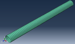
base model.png

This model is partitioned into 60 equal sections, with a node posisitioned at the centre of each section (centre of mass). I have then applied a structural distributing coupling constraint on each centre node to the surrounding shell structure section.

Then using a Guyan reduction I have reduced the stiffness matrix to the centre nodes of the shell (centre nodes selected as masters). The reduced model has 360 DOF.

For the mass matrix I have used the Guyan transformation matrix and reduced the full mass matrix, and also I have also used lumped masses at on the nodes with the mass properties of each section obtained in ABAQUS.

With the approach of reducing the full mass matrix, I do get the bending modes of the structure, however, I also get loads of other modes corrosponding to the centreline motion the shell modes that I was hoping was going to be removed in the reduction.

Using lumped masses gives a worse result, where none of the modes makes sense and are confusing. There doesnt appear to be any bending modes in the reduced model following this approach.

Am I approaching this the wrong way? is there a better way to approach the reduction such that there are only bending modes remaining?

Any help would be appreciated!
 
Replies continue below

Recommended for you

Couldn't you just create a custom beam section ? This is supported in Abaqus - you can provide the section constants for an arbitrary section if you know them or use a meshed section (create and mesh a 2D part representing it and generate the constants). What is the purpose of this model ? Is it meant for some further dynamic analyses ?
 
yes, a 2D beam element with a circular cross-section. But your post-FEA analysis will need to consider the various modes of failure of a tube (which may be different to a stable cross-section). What is the geometry (radius, thickness, length) like ?
 
Your simulation objective is not clear, so it is not easy for us to orient towards a good modelling strategy. By the look of your model and assuming you checked the properties, if you do not get mostly bending modes, either your section is very specific or your are looking at quite high frequencies.

If you want a beam behavior, you can actually model your system as a beam (with assumptions on the section), using a custom beam section.

Using central nodes to reduce your problem is not an advisable strategy, unless you are trying to connect this part to something else, without needing/having the possibility to precisely model the connection interface. In such case, you can use distributing coupling to model a coupling associated to loads. Note that distributing coupling is quite specific as your center node is slave and is constrained to move as the weighted average of the master points. Displacements like ovalization will thus not be constrained, explaining the displacements you are describing. You can use kinematic coupling, but that will imply that your section becomes rigid for all connected points, that will likely give an inaccurate result.
 
Couldn't you just create a custom beam section ? This is supported in Abaqus - you can provide the section constants for an arbitrary section if you know them or use a meshed section (create and mesh a 2D part representing it and generate the constants). What is the purpose of this model ? Is it meant for some further dynamic analyses ?
I could do that and i will try that tomorrow, however, the approach i want to take is to reduce the shell model i have, moreso because the stiffness of the full model is well represented in a model with only beam modes.

Im not sure making a 2D beam element model with provide that accuracy.
 
yes, a 2D beam element with a circular cross-section. But your post-FEA analysis will need to consider the various modes of failure of a tube (which may be different to a stable cross-section). What is the geometry (radius, thickness, length) like ?
radius is around 3m, length is 70m, thickness around 3mm. So its a very long thin shell model.
 
Your simulation objective is not clear, so it is not easy for us to orient towards a good modelling strategy. By the look of your model and assuming you checked the properties, if you do not get mostly bending modes, either your section is very specific or your are looking at quite high frequencies.

If you want a beam behavior, you can actually model your system as a beam (with assumptions on the section), using a custom beam section.

Using central nodes to reduce your problem is not an advisable strategy, unless you are trying to connect this part to something else, without needing/having the possibility to precisely model the connection interface. In such case, you can use distributing coupling to model a coupling associated to loads. Note that distributing coupling is quite specific as your center node is slave and is constrained to move as the weighted average of the master points. Displacements like ovalization will thus not be constrained, explaining the displacements you are describing. You can use kinematic coupling, but that will imply that your section becomes rigid for all connected points, that will likely give an inaccurate result.
The objective is to comapre the response of the full and reduced models essentially just a large model reduction exercise. Im looking at relatively low frequencies <50 Hz.

I think a beam model will have to be the next step, i have tried to get the reduced model to work with no luck unfortunately.

Is there a way to match the beam stiffness properties to the properties of each section of the shell? i have the mass properties
 
"Is there a way to match the beam stiffness properties to the properties of each section of the shell? i have the mass properties" .... ? a beam element needs section properties (A, I) which might be "mass properties" ? but you should be able to calc these.
So you're looking for modal response ... Maybe a beam element won't give you the behaviour of the shell ? Do you see modes with the shell locally vibrating ?
This is a very thin wall tube ... is it pressurised ??
 
The objective is to comapre the response of the full and reduced models essentially just a large model reduction exercise. Im looking at relatively low frequencies <50 Hz.

I think a beam model will have to be the next step, i have tried to get the reduced model to work with no luck unfortunately.

Is there a way to match the beam stiffness properties to the properties of each section of the shell? i have the mass properties
Model reduction should not be considered this way. By adding coupling and trying to concentrate yours sections to central nodes, you are making assumptions on your section kinematics anyway so you're better off working with beams, that properly formalize assumptions and kinematics you are trying to approach.

Another model reduction approach would be to use a modal subspace, where you select your modes of interest.

To define a beam, you will need to define material properties and a planar section, ABAQUS should then compute the stiffness properties and mass/inertia terms based on the provided section and material. If you have varying sections, each beam element can be assigned a different section. That said if sections are very different close to each other even the shell assumption may not be suitable depending on the needs.
 

Part and Inventory Search

Sponsor