Continue to Site

Eng-Tips is the largest engineering community on the Internet

Intelligent Work Forums for Engineering Professionals

  • Congratulations GregLocock on being selected by the Eng-Tips community for having the most helpful posts in the forums last week. Way to Go!

Equivalent frame analysis question 2

Status
Not open for further replies.

Agent666

Structural
Jul 2, 2008
3,080
So I was working through trying to teach myself the equivalent frame method from ACI318, specifically looking at some of the examples in ACI421.2 related to flat plates. But for the life of me I'm not getting the same answer for Example 1 (see attachment below). In particular my main question is with calculating the equivalent column stiffness, does anyone agree with the ACI value, and if so where did I go wrong? I wonder if someone can take a look and see if they agree with me or if I've made some dumb mistake somewhere.

I will note that doing the analysis talked about for the unbalanced moment based on a accommodating a 0.75" drift gives me the exact same moment they get, so it leads me to believe I've made some mistake somewhere. But then I've reviewed a number of other examples I found online and in PCA notes and seem to be following the same procedure as far as I can tell with respect to undertaking an equivalent frame analysis.

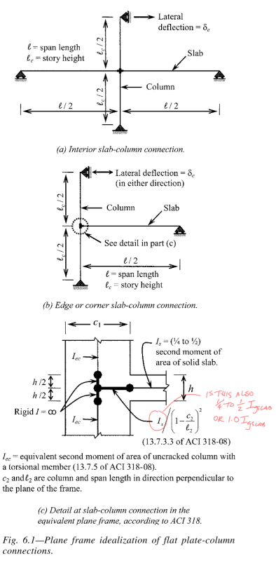
Next question for anyone familiar with ACI421.2, when doing the lateral analysis to determine the out of balance moment, just wanted to confirm whether the bit of slab modeled inside the column also has the 0.25-0.5 stiffness reduction applied as per the slab span outside of the column? EDIT the reason I ask this is initially I applied the reduction tot his region also, but the only way I can get the same moment as the ACI example is to only apply the 0.5 reduction beyond the column area and use full I_s in the column region
Annotation_2020-02-09_190855_usbfwr.png


Thirdly, in the example attached, one thing that makes no sense to me given I don't practice in the states and are not really familiar with the inner workings of US loadings codes, is that they are checking this column/slab connection for 2% drift but then they come up with 0.75" drift when the elastic drift or compatibility drift this connection will see will be 2% x storey height of 12' = 2.88" drift (i.e. same as shear walls in building). Why is the drift being reduced, seems illogical to me if the floor system is going along for the ride to 2% total drift as stated? For example they are stating at 0.75" drift these upper limits are not applying, but they sure as eggs will if you push it to 2.88" drift...

Thanks for any input!
 
Replies continue below

Recommended for you

Yeah I have the 2010 version, but up until a certain point in the standard it's talking about delta_u which is the total drift that the connection undergoes. Then all of a sudden it just says we only need to check the elastic part which is fundamentally incorrect as the frame goes along for the ride to delta_u. Evaluating the design actions at delta_e is not correct in my mind.

I'll update with the references to the earlier explanations involving delta_u next time I'm on my computer.

I'll check that divide by L-h/2 as had originally written it in terms of L being the total length - h/2 but may have stuffed up rewriting it to be L being the total length, but using that original definition got to exactly 1320 in^4 (and got the same answer as doing it manually via modelling it and applying unit rotation).

I'll look at your spreadsheet again, don't know why I wasn't getting the right answer... Probably that damn imperial rubbish [ponder]
 
"I'll look at your spreadsheet again, don't know why I wasn't getting the right answer... Probably that damn imperial rubbish"

To be fair the spreadsheet isn't exactly documented either. Here is some quick info on the spreadsheet:
Orange cells - User input
Green - Ka,Kb,Ca,Cb cells are the Stiffness and Carry over factors for a fixed-fixed condition

I know I indicate units in all the columns but if you use consistant units across the inputs you'll get the proper results, so you can ignore the imperial rubbish :).

Range E26 to Q35 is where I put the manual version of a two section calculation, for this problem we want K,far pin (Kfp) for joint A, assuming the section of infinite stiffness is entered in row 4, which should be cell P34.


My Personal Open Source Structural Applications:

Open Source Structural GitHub Group:
 
On the drift I agree that the frame will go along for the ride, but in ASCE 7 the inelastic drift, delta_u, is found by amplifying the drift obtained by an elastic analysis by a Cd factor. The example appears to be reducing the 2% ultimate drift to what the equivalent elastic drift would be by reversing the ASCE 7 procedure, so the analysis procedures are in line.


FYI Example 5 is Example 1 worked in SI units.

My Personal Open Source Structural Applications:

Open Source Structural GitHub Group:
 
I get what's going on regarding the ductile response of the main structural system and how delta_e and delta_u are related by the equivalent of a, ductility factor.

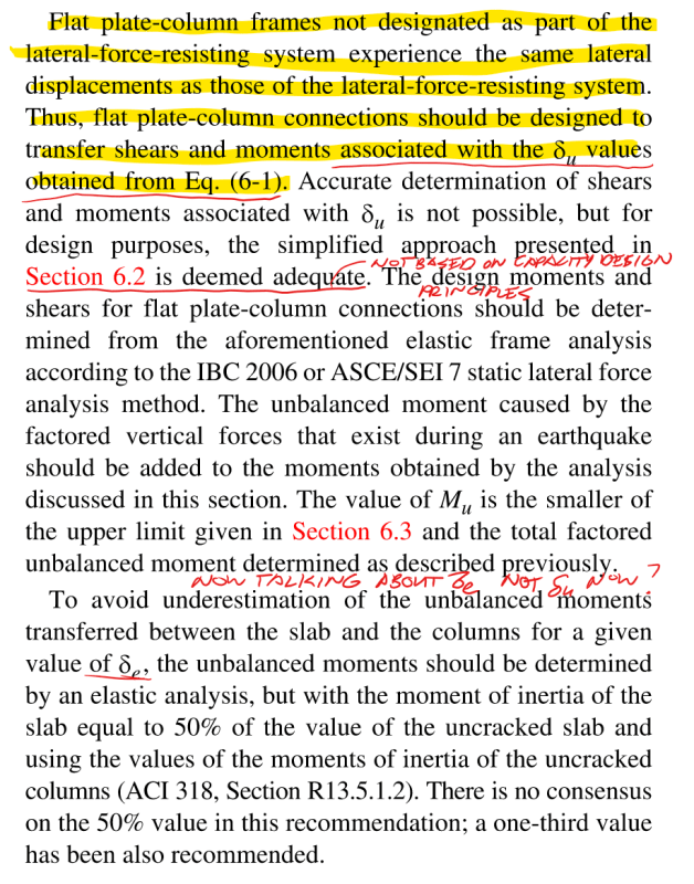
What I have a problem with is capping the design action in the secondary gravity system at the delta_e values for the main structural system. As it is flawed when secondary system carries on deflecting and eventually is limited by the upper limit of the slabs yielding as described in section 6 (from memory). Shows a fundamental lack of capacity design principles.

To throw some numbers at it to demonstrate, let's say the slab/column interface reaches the upper limit design actions at a drift of 2", but delta_u = 3.85x0.75"=2.8875". Therefore assessing the strength aspects for punching shear and shear reinforcement at a drift of 0.75" is flawed because under an ultimate limit state event in which the main lateral system reaches delta_u the secondary gravity system is still elastic up to 2" drift at which point you should actually be assessing the strength limit states for the secondary gravity system. So in the example quoted originally the strength should be assessed at the upper limit strength, not at the arbitrary 0.75" 'elastic' drift limit because the design actions keep increasing past this point until either the main system hits delta_u drift or the secondary gravity system hits its yield limit of the upper design limits.
 
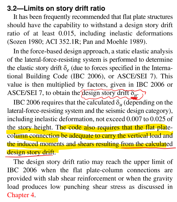
Celt83, just to follow up, if you refer to following extracts. This is basically saying what I am expecting, slab/column interface needs to be designed for actions resulting from achieving the design storey drift (delta_u).

But then later on in section 6 it reiterates this, and then in the following paragraph seems to move towards only checking delta_e drift which is just some arbitrary level of load as the true ductility factor for the main lateral system and the slab/column system could be quite different?!

I don't really agree that it is hard to estimate the moments and shears, in the case of the method presented it will be the upper limit actions unless the slab analysis results in a lower value at delta_u drifts. This is simply recognising that when the main system is at the full delta_u drift the slab is either yielding or its not. Capping this check at the delta_e drift is flawed in my view and could significantly underestimate the design actions for checking both the slab and columns. For example what if at delta_e + 0.1" drift you suffered a brittle punching shear failure. To get to delta_u drift as a system the slab/column interface needs to push past delta_e drift level.

Annotation_2020-02-16_134520_elm6gx.png

Annotation_2020-02-16_150127_hy2rjp.png


In response to the why am I dividing by 'L-h/2'? This is an error you are right!!
Going back an checking, this should be η = 3*(L)^3/(L-h/2)^3
and Σ Kc = Σ η*EI/L
Where L is half the storey height.

Actually noted as well if I put exact decimal conversions I also get to the same I_ec=1322.05in^4 answer you got via an alternative method.

If I had 406mm instead of 406.4mm for the column size for example and some other similar rounding on other values I fluked 1320in^4 exactly as the answer! So agree there must be a small degree of rounding going on or compounding loss of accuracy in individual answers when the original authors worked through it. Noted on Example 5 being the same, hadn't read that far.

Wish textbook examples wouldn't do this as makes it hard to replicate exact answers in this day and age of electronic calculations and 15 decimal place accuracy, especially when important steps are skipped in the working and you're ending up with a similar answer but not exactly the same!

Yeah I was clearly looking at completely the wrong part of your spreadsheet it seems in going back and looking at it again!
 
Celt83 said:
For question 2 I'd say as it is defined in the document should be 0.5*Is but I've seen several examples that also use 1.0*Is within the slab column joint.

If you do the analysis, you only get the unbalanced moment they call out in the example if you set the slab/column joint to 1.0*Is multiplied by the (1/(1-(c_2/l_2)^2)) factor. It's sufficiently different to say this was the intent. But who knows there may have been some unwanted rounding here too. My first instinct was to reduce it by the 0.25-0.5 stiffness reduction factor as well, that was until I worked through the example and got a different answer.
 
Status
Not open for further replies.

Part and Inventory Search

Sponsor