Continue to Site

Eng-Tips is the largest engineering community on the Internet

Intelligent Work Forums for Engineering Professionals

  • Congratulations waross on being selected by the Eng-Tips community for having the most helpful posts in the forums last week. Way to Go!

Equivalent Nodal forces of a multiple loaded beam?

Status
Not open for further replies.

PPoyyyy

Structural
Mar 22, 2017
6
So i have to do the stair analysis by hand , And i couldn't find the equivalent nodal forces on the inclined beam
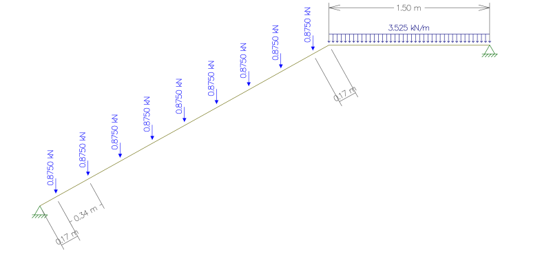
stairs__0001_dldwcc.png

Is there a way to do that without cutting the beam to several parts?
If not, Is there a way to turn the point loads into uniformly distributed?
Edit: What i want is to find the reactions so i can do a Buckling analysis on the inclined member and design the transversal beam that holds them.
 
Replies continue below

Recommended for you

For that layout I would suggest your point loads divided by the point load spacing = an equivalent uniform load.

Check out Eng-Tips Forum's Policies here:
faq731-376
 
do you mean you want to transform the inclined forces to their normal and parallel components ?

how to replace an array of uniformly pitched forces with an equivalent distributed load ... nP/L ?

another day in paradise, or is paradise one day closer ?
 
What do you want to do ?????
Design the stair beam ?
Calculate the forces in the beam ( Moment Shear .... )
Calculate deflections.....

For a hand analysis it is usually easier using single point loads rather than distributed line loads


best regards
Klaus
 
What i want is to find the reactions so i can do a Buckling analysis on the inclined member and design the transversal beam that holds them.
 
Buckling should be no problem ( what type of material ?? )

Are both supports fixed horizontally ??
if not then the system is statically determined and you can calculate support forces very easy by hand


best regards
Klaus
 
Yeah i kinda figured that would be the case..But i have to check for it , Material is Steel and both members are Pinned.
Now that i think about it what should be the other support on the inclined beam if i wanted to isolate it for buckling check?.
Thank all for the help Guys :)
 
You could convert the point loads on the sloping part to an equivalent uniform load as JAE said and calculate moment and deflection using standard formulas (wl^2/8 for moment and 5wl^4/384EI for deflection) and I think that would work assuming the stringer and landing beam are the same member. I typically like to use a roller at the end of a stringer to avoid counting on it for axial load but if you have adequate rigid horizontal connections at each end I don't see any reason you couldn't factor that into your analysis to give you some extra capacity. In any case, I would make sure you have an adequate moment connection at the kink.
 
Status
Not open for further replies.

Part and Inventory Search

Sponsor