D.E.N.
Structural
- Apr 22, 2021
- 31
Has anyone on here used (or heard of) the "Equivalent Truss Method" for diaphragm design? I believe the idea was originally proposed (or popularized) by J.M Scarry in New Zealand specifically for designing irregular shaped semi-rigid concrete diaphragms. I've attached one of his papers for reference. Essentially, the Truss Method is similar to strut and tie theory with some simplifications. It is really helpful for determining force concentrations at reentrant corners and openings in irregular shaped diaphragms, where the traditional "girder/beam analogy" for diaphragm design does not apply. It is an alternative to pure FEM diaphragm design, which IMO spits out hard to process stress contours at best.
I successfully used this "truss method" to design an irregular shaped concrete diaphragm on a 5-over-2 podium structure and locate chord steel at internal stress concentrations. On the same building I am now trying to design the even more irregular shaped wood diaphragms which all have to be modeled as semi-rigid, since there are a lot of cantilevered diaphragm areas (very few exterior shear walls). I found another paper building on the "original truss method" for concrete by Daniel Moroder (also from New Zealand) that outlines a "truss method" for wood diaphragms. Attached here for reference as well. Conceptually, the procedure in the paper makes sense to me, but what I am getting hung up on is the that some of the units for the "truss elements" don't exactly work out (specifically the cross sectional area of the diagonal element and the equivalent E & G values). They even address this in the paper, but I don't think they provide enough explanation of why that is ok or how to fix it.
I have not seen this method referenced or mentioned outside of the few resources I found from New Zealand and it does not seem to have much "support" from the engineering community or maybe just not enough exposure outside of NZ. To get to the point, I am a structural engineer in the US trying to adapt the truss method for use with my irregular semi-rigid wood diaphragms and need all the experts on here to weigh in on whether they think this is a good idea or not. Let me know if you think it makes sense conceptually and if so, what are your thoughts on the weird units for A, E, and G on page 164 of the wood paper?
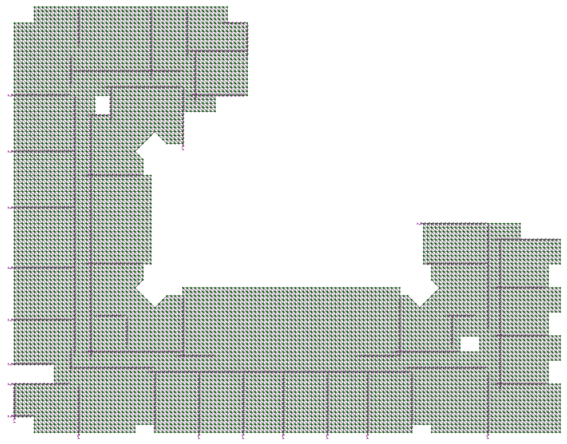
I have built a model in RISA 3D (a 2D model though) that has a 2'x2' bay spacing for all of the truss elements. I have modeled all of the floor trusses, joists, and top plates in there respective locations to represent the chords, collectors, and drag struts for the diaphragm. The remainder of the truss elements are comprised of the floor sheathing transverse to the floor trusses and the diagonal floor sheathing elements as described in the paper. I am hoping to run the model and identify areas where the transverse truss elements need to be replaced with something more substantial like blocking and simpson straps. I have the shearwalls all modelled in as spring supports to more "accurately" represent the global stiffness of the building for force distribution purposes. I am mostly hung up on what values to use for the transverse and diagonal truss elements (cross sectional area and equivalent modulus of elasticity is all I really need I think).
Project info:
- 5-over-2 podium building
- stick framed wood over concrete
- 3/4" advantech floor sheathing for diaphragms
- wood floor trusses @ 24" oc for most of the floor framing, 2x10 joists for the corridor framing
- SDC = B, wind loads control all directions
- building loosely represents an "L" shape and is about 268'x213'
Screenshots:
- Truss elements in RISA 3D (little springs represent shearwall "supports")
Resources:
- Concrete Truss Method: [URL unfurl="true"]https://res.cloudinary.com/engineering-com/image/upload/v1663704562/tips/Floor_diaphragms_and_a_truss_method_for_their_analysis_txjp0w.pdf[/url]
- Wood Truss Method: [URL unfurl="true"]https://res.cloudinary.com/engineering-com/image/upload/v1663704577/tips/Moroder_Daniel_Final_PhD_Thesis_gz8ect.pdf[/url]
I successfully used this "truss method" to design an irregular shaped concrete diaphragm on a 5-over-2 podium structure and locate chord steel at internal stress concentrations. On the same building I am now trying to design the even more irregular shaped wood diaphragms which all have to be modeled as semi-rigid, since there are a lot of cantilevered diaphragm areas (very few exterior shear walls). I found another paper building on the "original truss method" for concrete by Daniel Moroder (also from New Zealand) that outlines a "truss method" for wood diaphragms. Attached here for reference as well. Conceptually, the procedure in the paper makes sense to me, but what I am getting hung up on is the that some of the units for the "truss elements" don't exactly work out (specifically the cross sectional area of the diagonal element and the equivalent E & G values). They even address this in the paper, but I don't think they provide enough explanation of why that is ok or how to fix it.
I have not seen this method referenced or mentioned outside of the few resources I found from New Zealand and it does not seem to have much "support" from the engineering community or maybe just not enough exposure outside of NZ. To get to the point, I am a structural engineer in the US trying to adapt the truss method for use with my irregular semi-rigid wood diaphragms and need all the experts on here to weigh in on whether they think this is a good idea or not. Let me know if you think it makes sense conceptually and if so, what are your thoughts on the weird units for A, E, and G on page 164 of the wood paper?
I have built a model in RISA 3D (a 2D model though) that has a 2'x2' bay spacing for all of the truss elements. I have modeled all of the floor trusses, joists, and top plates in there respective locations to represent the chords, collectors, and drag struts for the diaphragm. The remainder of the truss elements are comprised of the floor sheathing transverse to the floor trusses and the diagonal floor sheathing elements as described in the paper. I am hoping to run the model and identify areas where the transverse truss elements need to be replaced with something more substantial like blocking and simpson straps. I have the shearwalls all modelled in as spring supports to more "accurately" represent the global stiffness of the building for force distribution purposes. I am mostly hung up on what values to use for the transverse and diagonal truss elements (cross sectional area and equivalent modulus of elasticity is all I really need I think).
Project info:
- 5-over-2 podium building
- stick framed wood over concrete
- 3/4" advantech floor sheathing for diaphragms
- wood floor trusses @ 24" oc for most of the floor framing, 2x10 joists for the corridor framing
- SDC = B, wind loads control all directions
- building loosely represents an "L" shape and is about 268'x213'
Screenshots:
- Truss elements in RISA 3D (little springs represent shearwall "supports")
Resources:
- Concrete Truss Method: [URL unfurl="true"]https://res.cloudinary.com/engineering-com/image/upload/v1663704562/tips/Floor_diaphragms_and_a_truss_method_for_their_analysis_txjp0w.pdf[/url]
- Wood Truss Method: [URL unfurl="true"]https://res.cloudinary.com/engineering-com/image/upload/v1663704577/tips/Moroder_Daniel_Final_PhD_Thesis_gz8ect.pdf[/url]