Eng-Tips is the largest engineering community on the Internet

Intelligent Work Forums for Engineering Professionals

ErrElemAreaSmallNegZero when using shell mesh

Status
Not open for further replies.

MegaStructures

Structural
Sep 26, 2019
366
0
0
US
I have a error that is driving me mad. I have created a model of an HSS connection using shell mesh. For some reason where two HSS meet eachother I am getting an error that

1) Mesh is distorted
2) There are zero area elements

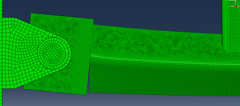
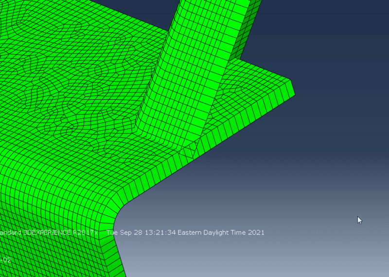
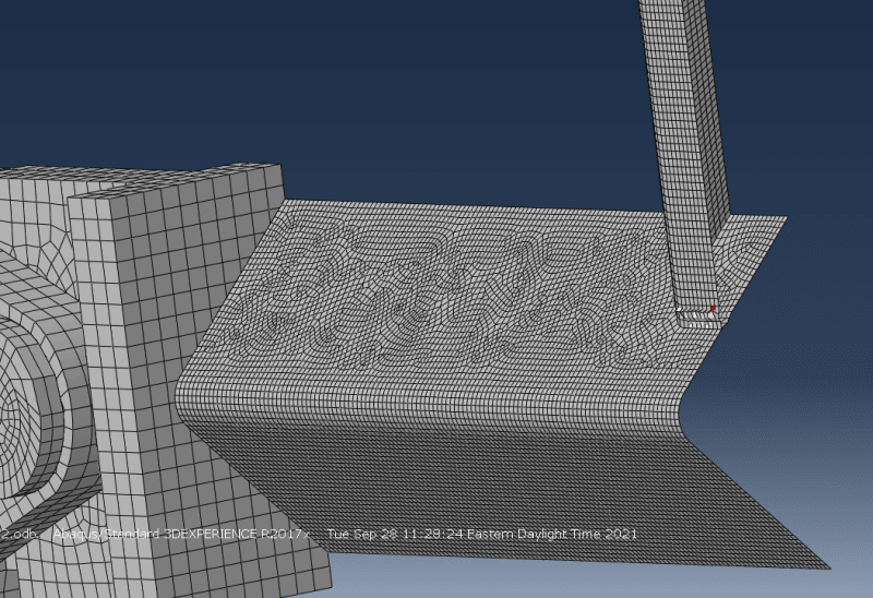
No matter how much I refine the mesh the problem doesn't go away. What could be causing this? The red element in the below picture is the only element with the second warning and the Abaqus model is attached.

ErrElemAreaSmallNegZero-01_n1xccr.png


“The most successful people in life are the ones who ask questions. They’re always learning. They’re always growing. They’re always pushing.” Robert Kiyosaki
 
Replies continue below

Recommended for you

No tie constraint there but it's almost certainly caused by overlapping shells (enable shell thickness visualization to see that) and general contact.
 
FEA way, thanks for the reply! How do you reckon I would have gotten overlapping shells in the model? Both HSS are one part and I "automatically" meshed the whole piece. I've re-meshed and changed seeds multiple time with no success. I did remove the part from the general contact pairs and now the model runs, but I have a new interesting problem! I defined a shell-to-solid coupling where the HSS meets the plate and the bottom of the HSS is separating from the plate. I refined the mesh on the plate thinking nodes weren't in the search distance and it still separates.

Shell-to-Solid Separation

Tie_Constraint-01_qn6ll6.png


Overlapping Shell Check

The shells do appear to be overlapping when thickness is turned on, but isn't that expected with the definition of mid-surfaces? Would that imply that shells cannot be connected at an angle like this?

ErrElemAreaSmallNegZero-02_iyehg4.png


FEA I must say you are a wealth of Abaqus knowledge and very helpful. Doesn't seem that there's a question on this forum that goes unanswered by you and a few others. Thank you

“The most successful people in life are the ones who ask questions. They’re always learning. They’re always growing. They’re always pushing.” Robert Kiyosaki
 
This connection is tricky because edge of the shell part is V-shaped and it's hard to align it with solid part's mesh. Try partitioning the surface of the solid part in such a way that both meshes fit together more closely.

Overlap of shell elements might be a problem in general contact because shell thickness is considered by contact algorithm and self contact might be detected here. Offset functionality may help you model this region. Another way would be to use solid elements for this connection and attach them to shells representing the remaining part of this structure with aforementioned shell-to-solid coupling.
 
Wow, that is really surprising that mid-surface shells cannot be connected at an angle like this. It seems like it would be a pretty simple connection!

“The most successful people in life are the ones who ask questions. They’re always learning. They’re always growing. They’re always pushing.” Robert Kiyosaki
 
I would check to see if any of your interactions have the "adjust slave initial position" option turned on. I have had the issue where this option was inadvertently turned on, and the adjustment caused some elements to collapse, resulting in the same error you're getting.
 
Indeed, that’s the most common reason for negative volume elements and thus I checked this first in the model attached by OP. However, in this case, there’s no tie constraint in the area with distorted elements and the problem is clearly caused by the overlap of shells and the way it’s treated by the general contact algorithm.
 
Status
Not open for further replies.
Back
Top