Continue to Site

Eng-Tips is the largest engineering community on the Internet

Intelligent Work Forums for Engineering Professionals

  • Congratulations SDETERS on being selected by the Eng-Tips community for having the most helpful posts in the forums last week. Way to Go!

Errors while designing a column (aci SP17)

Status
Not open for further replies.

Eng.007

Civil/Environmental
Sep 30, 2018
1
Hello all,
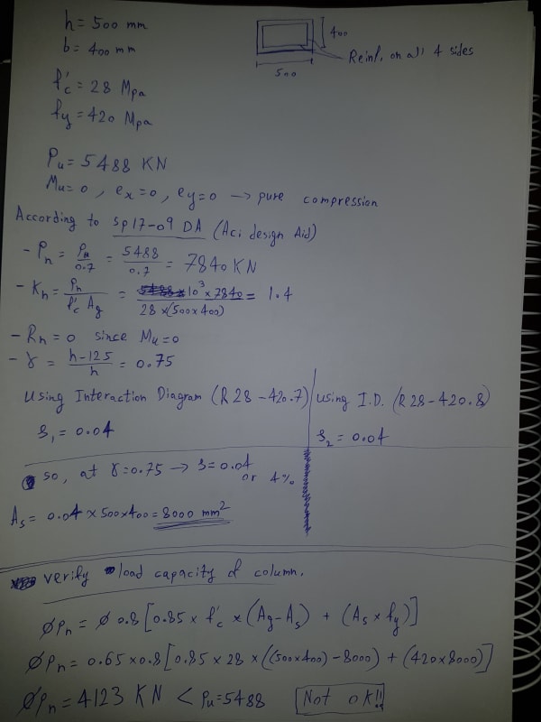
I have a question, I want to solve this problem using the same procedure as SP17 but once I'm done and want to verify my answer and find the column axial load capacity it comes out as inadequate. I'm aware if i dont multiply by 0.65 and 0.8 and rather use phi = 0.7 it comes at at the borderline. but how did aci solve it like that in their design aid? am i missing something?
so is it correct like that at 4% reinf? please help

my problem:
20190908_131130_nczkhn.jpg


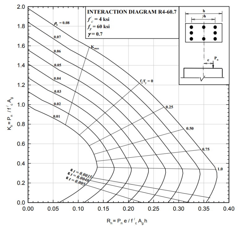
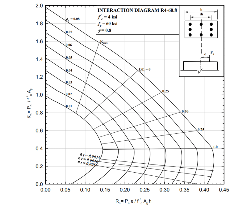
used interaction diagrams:

id1_wqi5ga.png


id2_imgs79.png
 
Replies continue below

Recommended for you

I think you are generally working through the procedure required, however some of your values are slightly out for using that interaction diagram. i.e. your gamma = 0.75 while the interaction diagram is 0.7 or 0.8 (though this will only make a difference once you need to consider moment as you'll see they all have the same intersection point on the y axis).

Similarly the 60 ksi bar strength is only 413.7MPa, not 420MPa. The interaction diagram way of working out strength is quite crude by its very nature, the errors in estimating a reinforcement ratio and slight differences in setout of reinforcement, etc, all have a corresponding effect on the calculated capacity when compared to a first principles analysis of the cross section accounting for the location of each bar and the actual strength of each bar. For example based on your K_n value of 1.4 the reinforcement ratio is actually more like 0.039 or so, little under or over estimates will mean you'll potentially never match exactly.

I think if you divided the axial load by phi = 0.7, then you should be using the same phi for working out the axial strength (i.e. not the 0.65 x 0.8). Otherwise you're comparing a reinforcing content worked out using 0.7 to a capacity applying alternative 0.52 factor which makes no sense. This is why using 0.7 gets you pretty close.

I find generic interaction diagrams are only useful for preliminary estimates of strength, ballpark calculations to establish initial member sizes if you like.

They are simply too inaccurate for real design or are basically useless for biaxial loading scenarios in my view.

You can however write a spreadsheet to work out the capacity based on a given reinforcement arrangement and column orientation, or resort to commercial software, you can even use this to generate your own interaction diagrams for say 420MPa vs the 413MPa. It's a useful exercise to familiarise yourself with the process of determining the section capacity.
 
I'd point out if you use reinf ratio of 0.039 and phi = 0.7 you end up with a capacity of 5495kN, so pretty damn close to the starting load of 5488kN!
 
Status
Not open for further replies.

Part and Inventory Search

Sponsor