Continue to Site

Eng-Tips is the largest engineering community on the Internet

Intelligent Work Forums for Engineering Professionals

  • Congratulations SSS148 on being selected by the Eng-Tips community for having the most helpful posts in the forums last week. Way to Go!

Estimate end reaction at Beam - Uniform Dist Load

Status
Not open for further replies.

cuky2000

Electrical
Aug 18, 2001
2,133
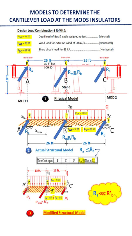
We need your help to help with an internal discussion among the electrical discipline to estimate the loads on a rigid bus with two spans with the uniform load as shown in the sketch below. This is a model that can be idealized as a beam with a uniform distributed load (Deadweight, wind, and short circuit)

Someone is trying to calculate the end reaction using a modified model reducing the span in half and following the recommendation on the IEEE Std 605 for a beam uniformed loaded. We are a little skeptical about questioning this method but do not have enough structural background to reject or accept this simplified suggested approach.

Can any structural colleague provide some advice on this matter?
Thanks in advance.

Rigid_Bus_Model_efcbs0.jpg
 
Replies continue below

Recommended for you

Are you treating the spans as simple span? What are your supporting beams? Regular rolled sections? Curious mimes want to know...

I cannot tell what the things at the ends of the span are, or the slightly sloped elements in the middle. [ponder]

-----*****-----
So strange to see the singularity approaching while the entire planet is rapidly turning into a hellscape. -John Coates

-Dik


The suggested method is against simple equilibrium rule of statics .
If the busbar is continuous ,
(q*L)
Ra =Rc = 3/8(q*L) (L is span length = 26 ft) and Rb=2*5/8(q*L) =5/4(q*L)

If If the busbar is not continuous , two simple span,

Ra =Rc = 1/2(q*L) (L is span length = 26 ft) and Rb=(q*L)


Regarding the recommendation on the IEEE Std 605 , can you pls post some excerpt ? will help to see the concept..


Tim was so learned that he could name a
horse in nine languages: so ignorant that he bought a cow to ride on.
(BENJAMIN FRANKLIN )

 
cuky2000 said:
Someone is trying to calculate the end reaction using a modified model reducing the span in half and following the recommendation on the IEEE Std 605 for a beam uniformed loaded.

I have IEE Std 605-2008. You are right to question this person's method. From my reading of the Standard (Paragraph 12.1.4 "Continuous Bus"), the "Modified Structural Model" shown is wrong. We can get into "why", if needed. Does not matter anyway, the insulator-support system shown is vertical.

Per Paragraph 12.3 "Simplified Evaluation of Insulator Cantilever Force", only wind and short circuit loading are considered (dead load and cable weight are not relevant).

Therefore, "Actual Structural Model" shown is basically right... but it needs to be "tipped over" 90 degrees to represent loading from only wind plus short circuit.

Solve for R1, R2 and R3, the insulator cantilever force:

Two_Span_Continuos-800_lyr3b4.png
 
Status
Not open for further replies.

Part and Inventory Search

Sponsor