Continue to Site

Eng-Tips is the largest engineering community on the Internet

Intelligent Work Forums for Engineering Professionals

  • Congratulations waross on being selected by the Eng-Tips community for having the most helpful posts in the forums last week. Way to Go!

Estimating Split Factor using Annex C in IEEE 80

Status
Not open for further replies.

mbk2k3

Electrical
Nov 18, 2010
97
Can someone explain to me how to apply Annex C for my particular application:

I have a 25kV line coming into my plant. Photo attached.

1. Does this line (see photo) count as a transmission line or a distribution feeder when it comes to IEEE terms within IEEE 80?
2. This line feeds a 25kV switchgear, and then a stepdown transformer. I assume the transformer isolates the utility side from any ground faults on the secondary side of the transformer. So does that mean that Category A from Annex C of IEEE 80 applies in this case? i.e. 100% remote and 0% local fault contribution?
3. Are Table C.1 and Figures C.1 through C.16 mutually exclusive? The example used in C.2 of Annex C doesn't make any reference to the curves in Figures C.1-C.16.
4. Does the configuration above quantify as "0 transmission lines, 1 distribution neutral" in the eyes of Table C.1?

PS - I've checked previous threads, but couldn't find a solid answer. They sort of roundabout addressed other items, but didn't give me a clear understanding of how to apply Annex C.
 
Replies continue below

Recommended for you

To better understand your system a simplified system configuration including the secondary feeder and transformer connection, ground faults and soil resistivity is suggested.
By inspecting of the picture, the following observation could be relevant to estimate the split factor:
• There is not shield wire on the incoming OH line. (No parallel to ground return path )
• It is unclear if the cable below is connected to the ground.
• There is most likely low net ground resistance on metallic UG return and moisture associated with the cooling tower and building where it is common to find water main, gas lines, concrete, steel rebar, etc.
Base on the above observation the split factor should be on the high side. Therefore, high ground fault current expected to flows between the grounding system and surrounding earth.
 
thanks cuky2000 for the reply.

the cable underneath the phase cables is the neutral return path, and yes it is connected to ground.
i thought that this return path is also considered a parallel ground return path that would divert some of the ground fault current away from the ground grid?

so back to the original question of how to estimate split factor (unless i'm going about this the wrong way completely?):
1. Does this count as a transmission line or distribution feeder w.r.t. IEEE 80?
2. The transformer is 25kV/4,16kV step-down wye-delta connected. So does that mean Category A from Annec C of IEEE 80 applies?
3. Are Table C.1 and Figures C.1 through C.16 mutually exclusive? The example used in C.2 of Annex C doesn't make any reference to the curves in Figures C.1-C.16.
4. Does the configuration above quantify as "0 transmission lines, 1 distribution neutral" in the eyes of Table C.1?

for what its worth, we do have soil resistivity and ground grid resistance checks planned in the next few weeks.
 
Yes, you would use Category A with a 25 kV ground fault. Treat the 25 kV line as a transmission line. It is the source of the fault current. The difference between a transmission line and a distribution line is that a transmission line is a source of fault current and the return current would flow in the transmission line shield wire back to the source. A distribution line neutral also will carry some of the return current, but it has to flow out of the neutral into pole grounds and through the earth to get to the fault current source. In your case, you would have no distribution lines.

I haven't used Annex C because my grounding analysis software (CDEGS) calculates the split. It looks like Table C.1 and Figures C.1-C.16 are alternative methods. Your case would be 1 transmission line, 0 distribution lines, but use the higher 100 ohm transmission ground impedance. It looks like IEEE screwed up the column headings in Table C.1. The last column should be Rtg=100; Rdg=200.

Cuky, I think that the lower conductor is a neutral, which would be treated the same as a shield wire for current split purposes.
 
It is my understanding that when using the Annex C tables "distribution lines" are for lines with a multigrounded neutral conductor, whereas "transmission lines" are those with a shield wire - the main differences being the assumptions used for the conductor impedance, spacing between grounds, and the ground footing resistance. To some extent line length also plays a factor, although after a certain point this has a diminishing effect on the collapsed/driving point impedance. All of the assumptions used to create the graphs are pretty clearly stated in section C.1. It is likely they won't apply exactly to your system, although may (or may not) be useful for some initial guidance on the current split factor.
 
I believe that the main difference between a transmission line and a distribution line with respect to current split is that:
[ul]
[li]The fault current returning in the transmission line shield wire has a metallic path all the way back to the source substation.[/li]
[li]The fault current returning in the distribution line neutral has to flow from the neutral into multiple pole footings and then back through the earth to the ground grid of the source substation [/li]
[/ul]
The 25 kV line probably has an impedance and length closer to that assumed for a distribution line, but there is no way in Annex C to take that into account. Assuming a longer length than actual for the transmission line would probably be conservative, meaning less current would flow in the shield wire than calculated.
 
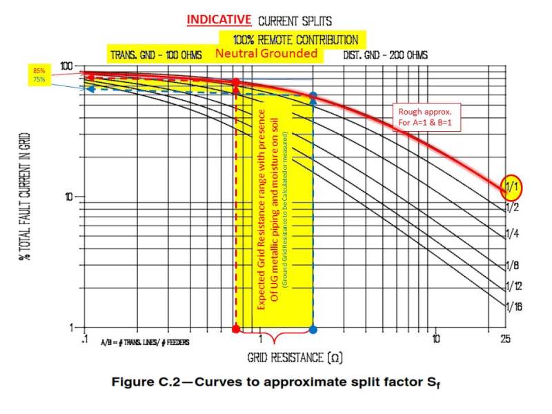
The prerequisite to use the graphic method to determine the split factor is that the system under consideration has to be reasonably similar to those covered by the graphic selected. Accurate result could be obtained by modeling the overhead neutral conductor in series with the underground cable shield wires, phase conductors, pole, etc. (For reference see Fig 32 of the IEEE Std 80-2000)
For illustration only, enclosed is a rough approximation of the split factor using a graphical method just with expected indicative high current split factor.
Split_Factor_wiz2rg.jpg
 
Here is something you might want to try as a sanity check for your calculations:

I use WinIGS software for grounding analysis.

It is quite powerful.

A very limited (compared to WinIGS, not to other short circuit programs) but free related program which is kind of a mini-version is available.

Search for "GEMI conduit" and you will find several links to the "GEMI" program. It runs on Windows or Linux using WINE.

The intended purpose of GEMI is analysis of wire or cables in steel conduit and program development apparently was funded by folks who want us to specify steel conduit.

With me, it achieved its intended purpose, I'm giving a lot more thought into EMI issues with cabling now, no more PVC everywhere because it's cheap and I am using more steel these days.

But GEMI can do a bit more than analyze cables in conduits. It doesn't do ground grids, but it will calculate the current in a conduit and/or a neutral or the static wire on a transmission line plus the currents into earth for a multi-grounded wye line if you have already otherwise calculated the ground grid and ground rod resistances. Available line models are quite limited compared to WinIGS and you can't modify the models but you may find something in the program that is reasonably close to your situation.

A minor learning curve is involved since the program does a lot more than a typical symmetrical components based short circuit program with the neutral/ground "Kron reduced" out of the matrix.

You will need information on the source feeder, if and how it is grounded, # of grounds/mile, and so on.

It can be hard (actually impossible) to get this info from your friendly local utility and this is where GoogleEarth with its measuring capabilities can be put to good use. Span lengths should be adjusted from actual if there isn't a ground at every pole, and there usually isn't, usually just those with transformers. If there are customer service grounds along the line you can add an estimate of these, but they may be unreliable since I doubt most electricians actually take a reading to see if the second ground rod is needed... If you can measure any ground rods or other electrodes at your facility with a clamp-on tester and reverse engineer the ground rod calculation to get an estimate of rho in your area. If you have a Megger DET/2 or similar so much the better.

With regards to the program I have uploaded a sample file with a multi-grounded 12kV line. You want to select "Network Analysis" then load the file. Select "Network Analysis" and put a L-G fault at Bus 2. Then use "Network Reports" to see all of the current flows for the fault. It is a bit messy but that is because there is so much information. Change the 1Mohm ground that I placed on the primary star point of the ungrounded wye - delta bank to 1 ohm or thereabouts and re-run the fault to see current into earth at the load end of the distribution line and at the source. You will find that with good grounds at both ends of a relatively short line the 25 ohm pole (assumed) grounds don't do a lot.

Dr. Meliopoulos may have given away a bit more of the store than he intended with this little GEMI program, or maybe not. A few hours spent with GEMI may make you really want to buy a WinIGS license.

Definitely (always) cross-check this or any other program with your manual calculations or other methods. In my experience with WinIGS actual GPRs are less than estimated by the manual calculation methods which is reasonable since manual calculations are intended to be conservative.

I think this use of the GEMI program is within the license provisions but follow your own conclusions on this point. Since I have WinIGS I have used GEMI just for small problems needing a quick answer when I am away from the office computer or of course for conduit design.

Hope this helps.

One more thing, do try out out the conduit analysis tools and check out the research literature on the benefits of steel. If you include a steel conduit in a network simulation expect to wait a while for the answer. It's a non-linear problem, lots of number crunching.

 
 file:///home/mfeller/Desktop/WYE-DELTA---12KV-SOURCE.NMF
Status
Not open for further replies.

Part and Inventory Search

Sponsor