I had a crack at doing something similar a few years ago, but between Revit and ETABS using Dynamo. I'll point out some issues you'll want to keep in mind when using any sort of tool to transfer between Rhino and ETABS:
Slab setdowns and minor penetrations - if the architect has modelled them in, they'll need to take them out/make the setdown level marry up with the floor level so as to simplify the model (unless they're large setdowns/penetrations). But - and here's the fun bit - you'll want to keep the setdown block/mesh in the model (i.e., don't join it with the rest of the floor mesh)so that it transfers to ETABS as a separate shell element. This will allow you to put in different loads in setdown areas if required.
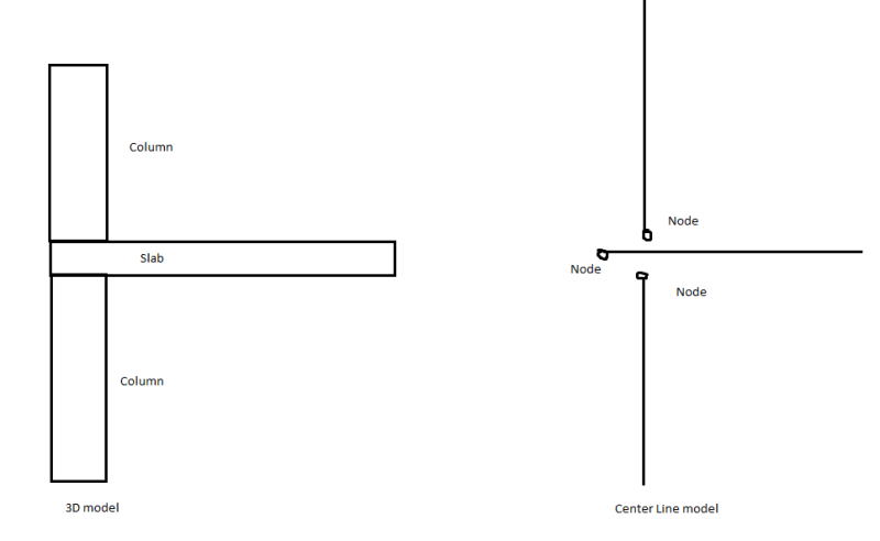
Column to slab connectivity - This is a big one. You'll need to know how the Rhino model has modelled the connectivity and then make sure the tool you're using is correctly translating that connectivity into how you'd want it in the model. I've pasted below an image showing an example of how it is done sometimes and what issues that causes:
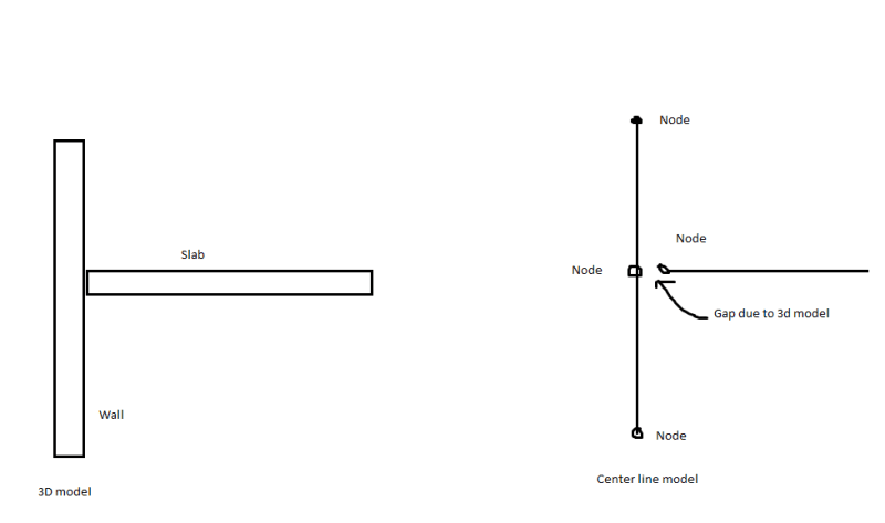
Wall to slab connectivity - Another big one, though similar to the one above. In my experience, walls are usually modelled as continuous, with the slabs connecting into them. This will cause a gap to appear when converting from 3D to center-line models.
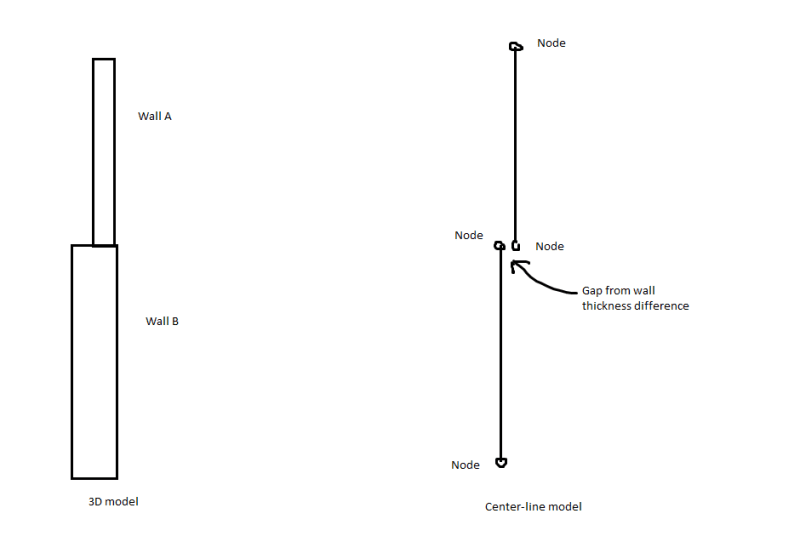
Wall to wall connectivity - If you're just using center-line connectivity between walls, you'll get eccentricities between walls of different thicknesses:
This one is a tad dangerous for walls. You may be thinking that the gaps can be rectified using stiff links or displacement constraints. This would be mostly fine for slabs, but for walls this can give rise to unintended stress concentrations at these locations if you don't model/mesh them properly. This problem is exacerbated by the fact that ETABS's meshing is not very good so you really can't model it properly (I'll admit I haven't used ETABS's latest and greatest version so I might no longer be correct about ETABS's poor meshing capabilities).
Beam centerlines - Beam centerlines will need to be dragged up to the level of the slab shells in ETABS. Also, you'll need to be careful with beam sections if they're being automatically created from the model. Sometimes architects will simply model a beam as an outcropping below the slab (i.e. they will not include the slab depth in the overall beam depth) and this might not be picked up by your tool.
Cutting slabs/shells along load patch lines - This is something I used to have to do when modelling floor shells in ETABS. The idea was to manually introduce a separation in the mesh between areas with different loads. However, I believe there is now a function that allows 'load patches' to be defined such that we don't need to cut the slabs. But if the load patch function doesn't work as intended, you'll need to fall back onto this.
Removal of non-structural steelwork/awnings/canopies etc. - You'll need to get the architect to remove any such steelwork as it is not necessary for your initial model and will only complicate things.
Re available tools that can help you - others have already mentioned Konstru, but you could also have a look at Speckle. It includes connectors for both ETABS and Rhino. Also, it's open source:
Finally, re my attempt at revit to ETAB - we did use it on one project which used flat slabs (so beams were not an issue). We ended up only taking in the slabs and columns from the architect's concrete revit model. The walls were modelled manually as the eccentricity issues were taking too much time to resolve in dynamo.
My personal recommendation would be to weigh the issues I noted against the complexity of your model and the amount of time available to you. If the model is relatively regular (e.g. same floor layout across the whole structure, no transfers) and easily 'QA'able', you could go the script route. But for large, complicated models I would thoroughly recommend modelling it in manually.