Continue to Site

Eng-Tips is the largest engineering community on the Internet

Intelligent Work Forums for Engineering Professionals

  • Congratulations KootK on being selected by the Eng-Tips community for having the most helpful posts in the forums last week. Way to Go!

ETABS modelling Help!

Status
Not open for further replies.

eng.chix

Structural
Jun 22, 2022
9
I have a 2 storey steel office building in a high seismic zone. I’d like to model it in ETABS to analyze for the seismic loads. I’m running into issues with the model after applying gravity loads only.
The basis of the structure is as such:
- fairly rectilinear
- HSS columns (potential to change to W sections if required)
- Steel Decking at roof, untopped – supported on OWSJs and supporting beams
- Steel Decking at floor, topped – supported on OWSJs and supporting beams
Questions:
1. Is it possible to model OWSJ’s in ETABS as secondary members? If so, how? (I’m currently showing W beams until I determine otherwise)
2. When I run the gravity load combination on the model with a substitute concrete slab in place of the steel deck, the gravity loads behave as I’d expect gravity loads to behave – vertically. If I just have the steel deck w/ or w/out topping, the deflected shape appears to be moving laterally and not vertically. Is there something I need to manipulate within the model so it recognizes the steel deck?
3. When the model starts to run, I keep having an error pop up referring to moment side plates. I’ve released all the moments in all the beams of the model, so I’m not sure why its still assuming moment connections.
I will attach my model for investigative and discussion purposes.
Any feedback is welcome!
 
 https://files.engineering.com/getfile.aspx?folder=54b08ed4-674a-4499-a5e1-e91efc9fad12&file=Model.EDB
Replies continue below

Recommended for you

1. Is it possible to model OWSJ’s in ETABS as secondary members? If so, how? (I’m currently showing W beams until I determine otherwise)
First, you can import the entire SJI joist database. You know that right?

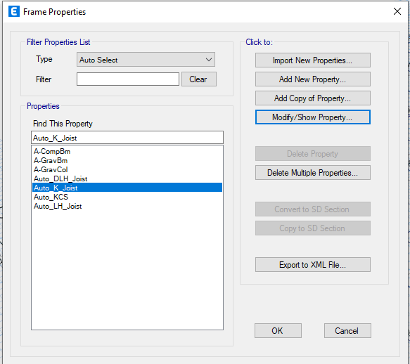
If you're in Frame Properties, you just select import new properties, then select the section shape as "joist section".

I usually then make sure there is an "AutoSelect" list for the type of joist I want to use.
image001_ajoib8.png


You should be able to then select this AutoSelect list when drawing your secondary members.

I'll look at your model itself in a bit to see if I can answer your other questions.
 
2) Your model is unstable as it is built. You do not yet have any moment frames. You will have to change the end releases for your main lateral frames to make it stable.... Either that or add some vertical bracing or shear walls or something. Anything to give it some lateral stability.

3) For B7 on both levels you have (accidentally?) used the Frame Assignment - Moment Frame Beam Type to call this beam out as a "SidePlate" connection. Which is odd because it's still got moment releases at both ends.

Note that for the SidePlate and Reduced Beam Section options, this assignment is used to turn the beam into a "non-prismatic" member. By that I mean that it's properties vary along the length of the member. For RBS beams, this will tend to increase the drift of the structure. For SidePlate connections it will tend to decrease the drift.
 
Thank you @JoshPlumSE !
That is most helpful! I've added braces to my model now, as well as checked that I have the moment frame beam type corrected. My model is still showing as unstable.
My next thought is that it might be coming from my diaphragm or steel deck definition. I've set the diaphragm to rigid.

Is there a way to define the steel deck, filled definition without including shear connectors? I'm trying to avoid those.
 
To investigate an instability, I usually switch from the advanced solver to the standard solver. This is because the analysis log gives better error messages. When I do that for your model I get the following flags.

analysis_log_y4obhu.png


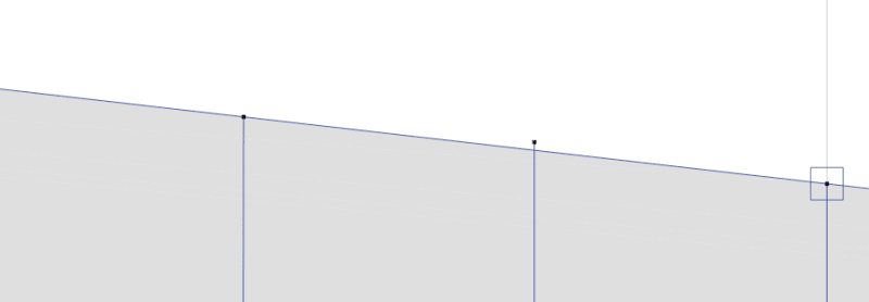
You see the location of the instability. When I zoom in on that location I see the following:
mis-aligned_joint_equvkx.png


If I select that joint and the two beams it's supposed to line up with, I can then use the Edit - Align Joints / Frames / Edges command to fix that problem. Then that instability should go away.


I haven't really looked at your diaphragm or your deck definition. But, based on the above, I'm pretty sure that's NOT what's causing the instability message. So, between the addition of the braces, moment frames, and correcting this misalignment, I'm hoping your instability issues go away.
 
Thank you!
That did clear up my instabilities.
I'm dancing the happy dance now!

Going back to the steel deck question, is there a way to manipulate the steel deck properties such that they don't show stud rails?
 
Going back to the steel deck question, is there a way to manipulate the steel deck properties such that they don't show stud rails?

Oh, I didn't realize this question was still unanswered. First, you've got the following.

- Steel Decking at roof, untopped – supported on OWSJs and supporting beams.

- Steel Decking at floor, topped – supported on OWSJs and supporting beams.

Neither floor should have "composite beams", correct? If so, all you have to do is select the steel beams, go to main menu bar and select Design - Overwrite Frame Design Procedure. That command will allow you to change the design procedure for those beams.
 
Thank you so much for all your help @JoshPlumSE!

The model works well now. The only issue I see now though is that, if I design with proprietary joists/deck, and enter the exact information into ETABS for deck and joist properties, I'm still seeing high deflections (approx 90mm), which doesn't jive with what I'd expect given that the loads and spans works well using the proprietary design data/software's.
I'd like to resolve this before I start completing the seismic design.

Do you have any ideas on what I could try to reduce these deflections without changing member sizes and deck thicknesses?

I've linked my model again for your reference.

Thanks again!
 
 https://files.engineering.com/getfile.aspx?folder=c6b725c1-0647-45f8-b80a-c8c81b632e7f&file=Model.EDB
I looked at the roof level and didn't see any real problems.

But, then I noticed relatively large deflections in steel beams that supported the joists. Especially at the lower levels. Now, I see that there are a number of 30K9's on the lowest level that have large deflections and that are declared to be inadequate for the applied loads.

For the sake of simplicity, I'll just focus on one of them B102 at the first level. DL shows a 34.6mm deflection (L/264), LL a 12.6mm deflection (L/726).

That would mean a total deflection of DL + LL of 47.2 mm (L/194).

Looking at the load diagrams we've got something like 12.1 kN/m of DL, and 4.4kN/m of LL. For a total DL+LL of about 16.5. Looking at the metric tables for a 30K9 that spans 9.144m (close enough!) the SJI tables show limits of 8.02 (black) and 7.92 (red). So, for live load we'd be okay. But, for total load, we'd be at about twice the capacity of a 30K9.

Let me see if I can back out the LL deflection based on the loading and the SJI tables. 7.92 kN/m for a joist this length should results in a deflection of L/360 = 25.4mm. But, since our loading is only 4.4kN/m the LL deflection should something like 4.4/7.92*24.5 = 14mm. That's reasonably close to ETABS' reported LL deflection of 12.6 mm. Especially since I've rounded off some numbers (length and loading) just to see if I was in the right ball park.

I think either this joist is undersized, or you've applied too high of a dead load... by a factor of two.


Status
Not open for further replies.

Part and Inventory Search

Sponsor