Continue to Site

Eng-Tips is the largest engineering community on the Internet

Intelligent Work Forums for Engineering Professionals

  • Congratulations KootK on being selected by the Eng-Tips community for having the most helpful posts in the forums last week. Way to Go!

ETABS Modelling Question

Status
Not open for further replies.

minx_kutor

Structural
Oct 15, 2023
9
I have a joint where 4 beams and 2 columns meet, this is a plinth level member without any floor. All of the are fixed with no releases. Intuitively one would assume that the shear in the column above would completely get transferred to the column below, however I see that a portion of the shear is going into the beam as tension?

The image to the left shows how the shear forces is transferred out such that the shear force sign itself changes.

I ran an iteration of the model with moment releases for the beams and I seeing the same behavior.

This is only happening in this level where there is no diaphragm, but the above floors where there is diaphragm this issue doesnt exist. Why is this happening? How do I avoid this?
Happy to provide the ETABS model.
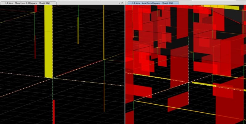
Capture_fndjn8.jpg
 
Replies continue below

Recommended for you

minx kutor said:
This is only happening in this level where there is no diaphragm, but the above floors where there is diaphragm this issue doesnt exist. Why is this happening? How do I avoid this?

I think you have to trace the load to see where it is going. It's got to be going into one of the beams, right? It probably means that the beam is dragging the load over to a stiffer column or shear wall or such.

For what it's worth, I've seen this sort of thing happen a lot in multi-story models. I generally will design / detail the lower column as if the shear did not transfer out of it. But, leave the analysis results the way they are.... provide, of course, they are indicative of a modeling error.

Also, I often find it helpful to look at the deflected shape for that load combination. Sometimes that makes it clear what areas are flexible and what areas are more rigid.
 
So there is no diaphragm, my only reasoning is that the beam in axial is more stiffer than the column in shear and hence the beam attracts the force? Does this make sense?

My question however is that the floor above has the same condition but there is a rigid diaphragm and we see no such behavior. I wanted to ask as to why it is happening.
 
Because there is a rigid diaphragm at the floor level, both the top of the lower column and the bottom of the upper column are forced to move the same amount as everything else and therefore the shear transfers directly. At the level without a diaphragm, technically the two column pieces aren't forced to move together, and therefore the shear load will take the path of stiffest resistance which the model is telling it is through the beam to another lateral load resisting element.

Does the analysis look the same if the two column sections are instead modelled as a single column for the full height with the beams framing in at a node somewhere along the length of the column? I'm not sure if that's possible in ETABS but I'd like to think it is.
 
It helped a little but not a lot. But it still doesnt solve the issue. Can I send you the model to look at?
 
Status
Not open for further replies.

Part and Inventory Search

Sponsor