Hi guys,
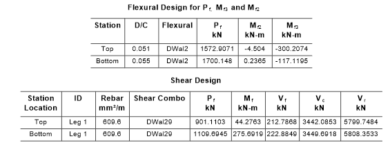
I am about to design a core wall and I am trying to validate by hand the ETABS Shear Wall design results based on Eurocodes.
Within the Design Load Combinations for the Shear Wall Design, I choose all my ULS load combinations (i.e. wind leads,live leads etc).
The thing is that I am struggling to understand how ETABS chooses the worst case scenario between the load combinations.
Does it choose the worst case load combination by checking which combination gives the highest moment?
I am a bit confused because during the Shear Wall Design, the axial load that ETABS takes into account its not within the table results for this specific pier and location. I have also removed the live load reduction factor but still the axial load of the design process doesn't match with the axial load of the corresponding load combination!
Regards

