Hi Eng Tips Community,
I am currently in the process of designing the lateral stability system of a 30 storey concrete apartment building. The main lateral stability element is a concrete core box with a few internal walls. Currently the diaphragms are all modelled as semi-rigid as there are outrigger systems and the floorplate is not a regular rectangular floor shape.
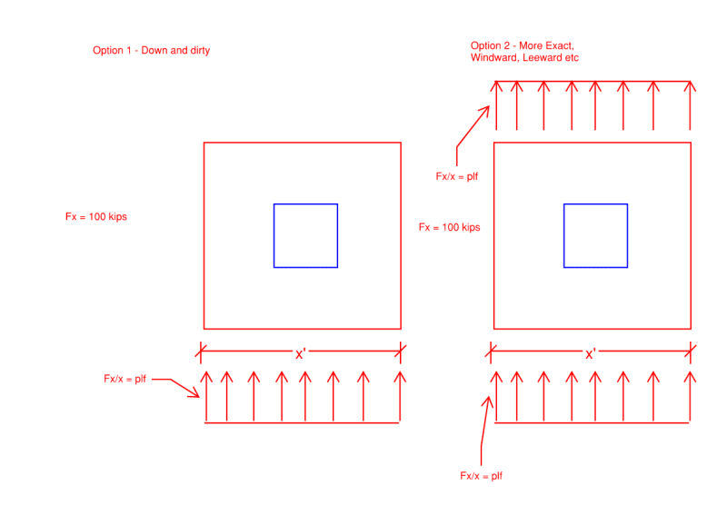
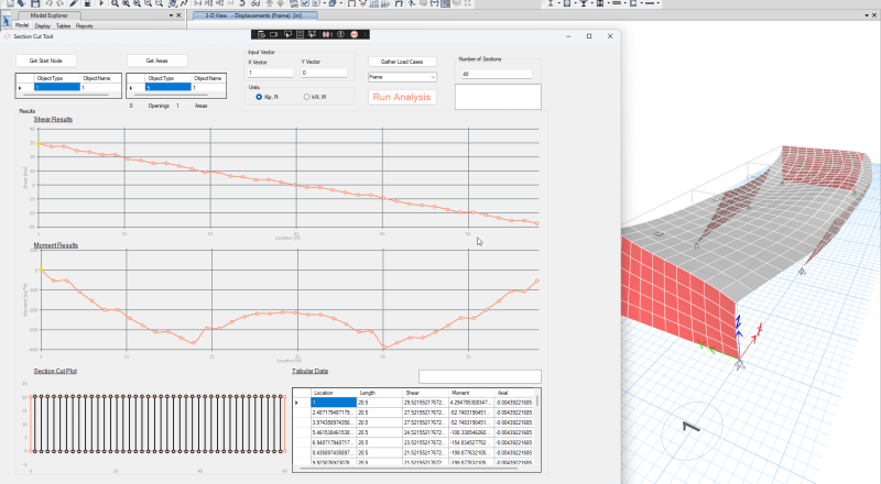
We have recently received wind tunnel testing results in the form of Fx, Fy and Mz forces which are to be applied at a specified point location within the slab/diaphragm. Upon inputting these loads into the model, we are seeing some unreasonably high tension stresses in a few of the internal walls which don't make sense to us. Upon further investigating, it seems like re-defining the diaphragms as rigid fixes the issue. It appears that ETABS does not distribute the loads correctly when inputting user defined wind loads at a single point within the floorplate when using semi-rigid diaphragms. My understanding is that with auto wind or earthquake loads, ETABS correctly distributes the lateral forces among multiple joints within the floorplate when using semi-rigid diaphragms.
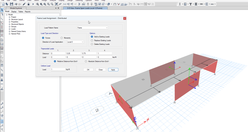
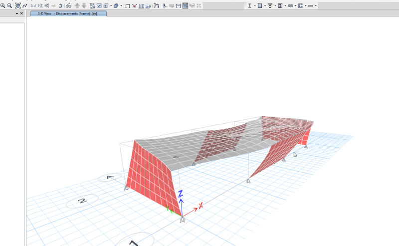
My question is whether or not there is a way to properly input wind tunnel test point loads while using semi-rigid diaphragms while distributing the load realistically to the core box.
Thanks in advance!
I am currently in the process of designing the lateral stability system of a 30 storey concrete apartment building. The main lateral stability element is a concrete core box with a few internal walls. Currently the diaphragms are all modelled as semi-rigid as there are outrigger systems and the floorplate is not a regular rectangular floor shape.
We have recently received wind tunnel testing results in the form of Fx, Fy and Mz forces which are to be applied at a specified point location within the slab/diaphragm. Upon inputting these loads into the model, we are seeing some unreasonably high tension stresses in a few of the internal walls which don't make sense to us. Upon further investigating, it seems like re-defining the diaphragms as rigid fixes the issue. It appears that ETABS does not distribute the loads correctly when inputting user defined wind loads at a single point within the floorplate when using semi-rigid diaphragms. My understanding is that with auto wind or earthquake loads, ETABS correctly distributes the lateral forces among multiple joints within the floorplate when using semi-rigid diaphragms.
My question is whether or not there is a way to properly input wind tunnel test point loads while using semi-rigid diaphragms while distributing the load realistically to the core box.
Thanks in advance!