Eng-Tips is the largest engineering community on the Internet

Intelligent Work Forums for Engineering Professionals

Evaluation of a +/- toleranced radius 1

Status
Not open for further replies.

Burunduk

Mechanical
May 2, 2019
2,335
0
0
IL
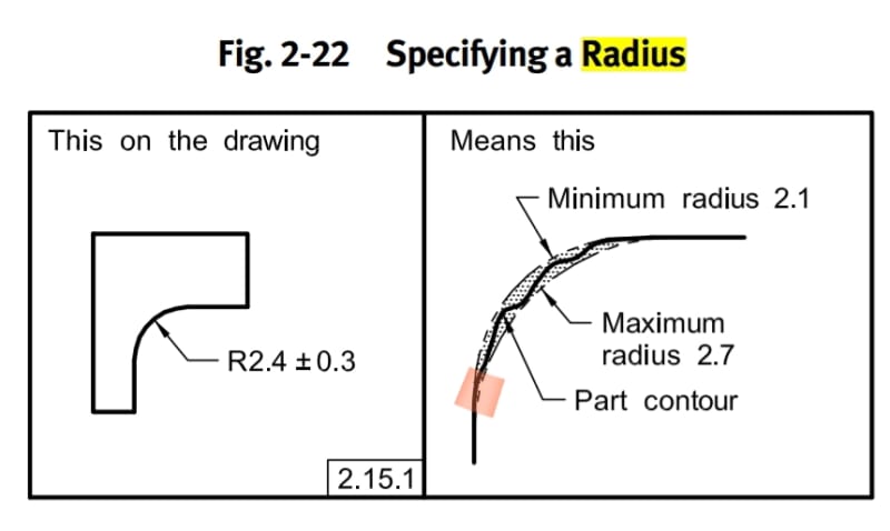
Fig. 2-22 in ASME Y14.5 shows a crescent-shaped tolerance zone that starts and ends tangent to 2 straight outlines of features that the radius connects.
When evaluating if an actual produced radius is within tolerance, what sets those 2 straight lines/planes? The actual produced "flat" surfaces will have flatness error, so how one aligns the theoretical tolerance zone with the actual part?

Consider that there is a potential deviation from the tolerance zone approximately around the marked area. The way the tolerance zone is overlayed on the part may be an important factor for whether to accept or reject.

20191003_123323_ltmqou.jpg
 
Replies continue below

Recommended for you

This was brought up in an article written by mitutoyo that I found very interesting. They argue that it's a very ambiguous way of dimensioning and almost impossible to define. Link
 
Great link!

We measure radii various ways. Sometime with an optical comparator in which case the above concerns are definitely a factor. Very hard to get exact, repeatable readings. Sometimes we can trace the part with a profilometer which I feel does a much better job and is more repeatable.

I try to dimension radii with either just a min or max value or with a generous tolerance except for the somewhat rare cases where it's really important. Most of those should be a CR (Controlled Radius) but that adds another layer of ambiguity!

----------------------------------------

The Help for this program was created in Windows Help format, which depends on a feature that isn't included in this version of Windows.
 
Burunduk,

ASME Y14.5-2009 para. 2.15.1 doesn't say the boundary arcs must both be tangent to a single pair of lines. I think it's reasonable to use a different pair of lines for each boundary.


pylfrm
 
Thank you, the three of you.
The Mitutoyo article is very interesting too.
pylfrm, could you expand a bit about your suggestion? Does it mean creating a uniform size boundary as in a profile control, as opposed to the crescent shape shown in the posted figure?
 
pylfrm, could you expand a bit about your suggestion? Does it mean creating a uniform size boundary as in a profile control, as opposed to the crescent shape shown in the posted figure?

It does not.

ASME Y14.5-2009 doesn't say anything about the location of the boundary arcs relative to each other or relative to the actual part. You have to start making things up if you want to correct that problem. If you want to invent some lines for the boundary arcs to be tangent to, I see no reason to limit yourself to a single pair.


pylfrm
 
FYI Y14.5-2018 does make a slight change to this and allows for radii which are concentric to each other or tangent to the adjacent surfaces depending on how they are defined.

That said, I think I think location of a concentric tolerance zone is likely problematic without a DRF specified. Its probably best to utilize profile if this is the behavior desired.

ASME Y14.5-2018 said:
5.16.1 Directly Toleranced Radius
When a radius symbol R is specified, a tolerance zone bounded by two arcs is created (the minimum and maximum radii). The part surface shall be within this zone. When the center of the radius is located via dimension( s), the arcs are concentric. When the center of the radius is not located (tangent located), the arcs are tangent to the adjacent surfaces and create a crescentshaped tolerance zone.
 
I suppose I think about this a bit differently than most... When I see the crescent shaped tolerance zone of a radius, I tend to think of it as more of a dimensional residuum, like a fractional remainder of sorts... Because the edge of the radius is tangent to two edges typically, the position/size tolerance of those edges determine the available variation of the radii at those points. Does that make sense? So, I'm saying that, because the edges where that radius starts is controlled by another tolerance zone, the effective tolerance zone of the radii is necessarily constrained to a gradually smaller and smaller variation.

There are probably instances where this way of thinking about radii is wrong, but this is how I typically see them implemented.

I'm not a vegetarian because I dislike meat... I'm a vegetarian because I HATE PLANTS!!
 
Status
Not open for further replies.
Back
Top