Eng-Tips is the largest engineering community on the Internet

Intelligent Work Forums for Engineering Professionals

  • Congratulations waross on being selected by the Tek-Tips community for having the most helpful posts in the forums last week. Way to Go!

Exact pumping

Status
Not open for further replies.

dimitp

Structural
Jan 12, 2015
12
0
0
SE
Hi All.

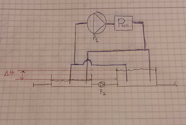
Im wondering if there is a way to pump water to and from 2 tanks without risking overflow in one tank, and without using any controll system like levelsenosrs or flow controlled valves?

My experience is that you will never get an exact 50/50 split of water i a T connection for example.
 
Replies continue below

Recommended for you

A sketch and some more detail would be nice here, but if I understand it you are pumping water to two tanks and want the levels to be equal (but you think hydraulics through the piping would never be exactly the same)?

If the tanks are at the same elevation, you could tie them together with a run of pipe below the liquid level from tank to tank and they would gravity equalize to the same level.
 
To and from two tanks via a pump? Closed loop just make sure both tanks are the same size and you don't have more than 90# of tank volume in the system?

For a T connection pumping TO or FROM TWO tanks, so long as you make the flat part of the T 2-3 times the size of the incoming line vertical up the Tee, then the levels will equalise providing the lengths of the pipe from the tee to the tanks is more or less equal.

A sketch would help a lot!


Remember - More details = better answers
Also: If you get a response it's polite to respond to it.
 
dimitp,

Agree with you. A lot of posts here from people that have never done it. Here is a real world example. Parallel symmetrical piping, but the water elevation is about 6-Inches off in these 85-Feet diameter wastewater tanks.

example_ajnvep.jpg


The only method to obtain a nearly perfect split is with a weir of some sort.

Another aspect to this problem is that the tanks are probably not constructed level.
 
You could use a rotary flow divider for accurate flow splits. I have never seen one for water, only oil but I can't see why they wouldn't make them for water.
 
Sort of along LittleInch's comment (I think)...

If the line to the tank or from the tank is large enough to keep the flow velocity low, and in the absence of check valves, I don't see why the hydrostatic heads in the tanks wouldn't act towards ensuring an equal flow / level split using a simple tee.

Of course, with both tanks at high level and no controls in place, if one was to continue pumping water into the tanks, they would overflow unless the high level hydrostatic tank (plus whatever internal pressure / head) exceeded the pump shutoff.
 
Because split flow into both tanks would only tend to equal levels at the vicinity of the tank inlets, which does not necessarily mean equal flows into each. If one tank had a larger outlet, or lower outlet, or unobstructed outlet, different current direction, etc. flow to that tank might be greater; even if both tanks had the same levels. Do paddles all turn clockwise? Control of what's going on inside the tank and at the tank's outlet's are equally as important as controlling the what's and how's about what enters them.
 
Hi again all. Let me clarify my question with a diagram:

bb_j2azys.png


I want to add one process to both tanks, This process is supplied with water by P1 from both tanks and drains from the process to both tanks.
The tanks have a height difference, Delta H. The tanks also communicate via pump P2. But pump P2 is not connected to P1 and P2 runs intermittently while P1 runs continuous.

To further specify my question: The goal is to not create an overflow in any of the tanks w/o controls, vales etc.

As stated by bimr: correctly sized T connections will never give good enough division in flow, especially if P1 is shut down for a weekend and P1 produces a high enough flow. The tank bottom levels can also vary.

What do you think? Thanks a lot for the replies this far!
 
The simplest solution is to allow the tanks to communicate via a line large enough to keep flow velocity low; just as others have suggested. However, if you do this it's not clear what function P2 would have. A sufficiently large line might just allow flow to circulate between the tanks. In effect P2 might just be a circulation/mixing pump for these volumes. There isn't enough info written here to know.

A straight forward solution that retains the pumping functions is to use a set of level switches to start/stop your pumps. A set of level switches to could be wired in directly for very small pumps, or could be wired in with a set of relays/contactors for larger systems. This would not minimize delta H, just prevent overflow by pumping. It would add components which are level devices, but it's often easier and cheaper to do that if compared to more complicated piping and valve systems.

If overflow is a significant impact, I wouldn't trust any single switch. Redundancy would be needed.

If your goal is to minimize delta H, you will need some more sophisticated control.
 
Thank you for all the answers.
I to have come to the conclution that a level switch is the only good option. i just wanted a second opinion.

/D
 
Status
Not open for further replies.
Back
Top