Continue to Site

Eng-Tips is the largest engineering community on the Internet

Intelligent Work Forums for Engineering Professionals

  • Congratulations cowski on being selected by the Eng-Tips community for having the most helpful posts in the forums last week. Way to Go!

Examples of Equivalent Dimensioning & Tolerancing Schemes

Status
Not open for further replies.

pmarc

Mechanical
Sep 2, 2008
3,227
Hi,

Throughout the years I have come to a conclusion that in general there are not many examples where changing dimensioning and tolerancing scheme from one to another would keep the geometric requirements for the system unchanged.

One example where this conclusion would not be true is changing from perpendicularity wrt A to total runout wrt A when applied to a flat face normal to datum axis A.

Another one would be a simple bushing where its ID and OD are controlled with the same +/- tolerance, and then it does not really matter which of the features will be datum feature A and which will be controlled with position or runout relative to A.

I have some more, but I would like to see what others can offer. So could anyone share some examples?
 
Replies continue below

Recommended for you

pmarc said:
What about <CF> modifier? Would there be a way to define the same requirement without using the <CF> symbol?

In many cases, something similar could be achieved with [box]position[/box][box]0 (M)[/box] SEP REQT or [box]position[/box][box]diameter 0 (M)[/box] SEP REQT. I only say similar because there might be a difference in the determination of actual local size, depending on the definition you feel like using.


pmarc said:
Any other ideas?

ASME Y14.5-2009 Fig. 2-5: Remove dimension origin symbol, make dimension basic, identify datum feature, apply profile tolerance.

ASME Y14.5-2009 Fig. 4-5: Change perpendicularity to position and remove references to datum features B and C.


pylfrm
 
pmarc said:
What about <CF> modifier? Would there be a way to define the same requirement without using the <CF> symbol?

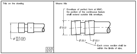
<CF> simply means that 2 or more features are sharing the same envelope:
Capture_1_eudhkk.png


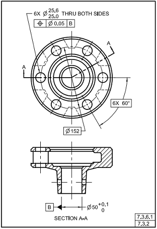
Similar effect may be achieved by note, declaring that 2 holes are in fact 1 hole - what are you going to do?
Capture_2_em2kcb.png


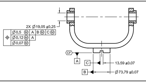
For <CF> that is not feature of size
Capture_3_lsipjb.png


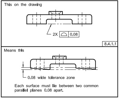
Profile for coplanarity will serve well:
Capture_4_iwotsc.png


"For every expert there is an equal and opposite expert"
Arthur C. Clarke Profiles of the future
 
Pylfrm,

pylfrm said:
I only say similar because there might be a difference in the determination of actual local size, depending on the definition you feel like using.

Could you, please, explain what do you mean by :"I only say similar because there might be a difference in the determination of actual local size, depending on the definition you feel like using."

I am trying to understand how the actual local size could be qualified/measured in different ways. Are there multiple ways to get the actual local size?

Thank you
 
pylfrm,

I want to hop on greenimi's question about what "definitions" you are referring to and also ask why the separate requirement callout is necessary? Wouldn't you want them to be held to simultaneous requirements?

Additionally, could you elaborate what you mean about figure 4-5? The only perpendicularity callout I see is on the single center boss of 25.1/25.0 and if you change that to position its only reference is to datum A already which would only control orientation which as far as I know is not acceptable with position.
 
pylfrm,
Like chez311, I am not sure I see a need for SEP REQT. Per my understanding this would do exactly opposite to <CF> concept - two or more features would become totally independent of each other.

Agreed on fig. 2-5.

As for proposed modification of fig. 4-5, I believe you meant something similar to this:
Am I right?


CH,
You may disagree with me, but I personally do not like the idea of using notes like THRU ALL or THRU BOTH SIDES to indicate that two or more features share the same MMC envelope. This is not "programmatic" way to say that continuous feature is the intent. By "programmatic" way, I mean a way that could be automatically consumed downstream (by CMM for example).

Agreed on the <CF> vs. profile equivalency in case of planar interrupted feature (although if possible, I would like to avoid discussion on whether use of <CF> modifier for non-features of size was really the committee intent or not).

Thanks.
 
pmarc,
You may be surprised but I share your opinion about Fig. 2-8 and 7-5. But they are right there in the standard and create "equivalent schemes".
Next on my list would be Translation Modifier.
It even comes with the gem like this: "When the translation modifier is applicable and the direction of movement is not clear, movement requirements shall be specified" (they also forgot to mention how)
Why bother to create control that may be "unclear", if the same standard offers Customized datum reference frames - the way to explicitly and unambiguously specify, which datum simulator should control which degree(s) of freedom?
Would you agree that Transition modifier can ALWAYS be replaced by Customized DRF?

"For every expert there is an equal and opposite expert"
Arthur C. Clarke Profiles of the future

 
pmarc,

I notice on that tech tip that on the central hole is called out with position to datum A in both versions of the drawing. My first instinct that in at least the first version, where the central hole is called out as datum B, that is incorrect as it only controls orientation and there is no other feature called with the same DRF (datum A only) for simultaneous requirement. Is my thinking correct? I know this topic comes up quite frequently so I am trying to get a handle on what is acceptable or not. I understand they may have done that for clarity - ie: only change the datums and DRF in each FCF to make their point, or are there other GDnT experts that don't seem to agree with that line of thinking?
 
chez311,
I would agree with your assesment.
 
pmarc,
You didn't convince me back then, you don't convince me now.
TM as shown on 4-19 can be replaced with CDRF no problem, so here is your equivalent scheme.
Could you be so kind to sketch the part and apply TM to it the way it cannot be replaced with CDRF?


"For every expert there is an equal and opposite expert"
Arthur C. Clarke Profiles of the future

 
CH,
Let me ask you this. If you were to use CRDF concept in position FCFs applied to dia. 9.2 hole and pattern of four dia. 5.1 holes in fig. 4-19, how would the FCFs exactly look like?
 
greenimi, chez311,

Instead of "determination of actual local size", I probably should have said "determination of compliance with the LMC limit". According to ASME Y14.5-2009, this is based on actual local size. Unfortunately the definition given for "size, actual local" is rather unclear. A more robust definition could be invented, but there is more than one way to do that.

ASME Y14.5.1M-1994 defines the meaning of size tolerances somewhat less ambiguously. Although issues remain, the intent seems much more clear. Here the LMC limit creates a boundary by sweeping a ball along a spine, and this would definitely lead to a difference between <CF> and the position tolerance scheme in certain cases.


pmarc said:
Like chez311, I am not sure I see a need for SEP REQT. Per my understanding this would do exactly opposite to <CF> concept - two or more features would become totally independent of each other.

I should have noted that the proposed position tolerance would be added to the specification of feature count and size tolerance, similar to the following:

2X diameter 22.1 - 22.2
[box]position[/box][box]diameter 0 (M)[/box] SEP REQT​

As I understand it, SEP REQT does not make the position tolerance apply separately to each of the two features in the pattern. It just ensures the position tolerance does not become part of a simultaneous requirement with other tolerances on the drawing. I included it for the sake of generality, but unfortunately it appears to have confused the issue.


pmarc said:
As for proposed modification of fig. 4-5, I believe you meant something similar to this:
Am I right?

Yes.


chez311 said:
Additionally, could you elaborate what you mean about figure 4-5? The only perpendicularity callout I see is on the single center boss of 25.1/25.0 and if you change that to position its only reference is to datum A already which would only control orientation which as far as I know is not acceptable with position.

I'm not aware of a prohibition on position tolerances that only control orientation. I realize this is a popular topic for debate, but I don't see a problem with it. Regardless, that is not the case in my proposed scheme. The three position tolerances would all be part of a single simultaneous requirement which controls location.


pylfrm
 
Using CF on a pair of interrupted surfaces (CH's snippet of Fig. 7-45) is not "equivalent" to using profile of a surface for coplanarity.

John-Paul Belanger
Certified Sr. GD&T Professional
Geometric Learning Systems
 
J-P,
In order to be fully defined the interrupted surface on CH's snippet would most likely have to be controlled with flatness tolerance. If the value of the flatness tolerance was 0.08, wouldn't this be equivalent to the datumless profile of 0.08?
 
pylfrm,
If you included SEP REQT to ensure "the position tolerance does not become part of a simultaneous requirement with other tolerances on the drawing", then I have no further comments to that.
 
pmarc said:
If you were to use CRDF concept in position FCFs applied to dia. 9.2 hole and pattern of four dia. 5.1 holes in fig. 4-19, how would the FCFs exactly look like?

Somehow like this:

Capture_1_lhlnww.png


"For every expert there is an equal and opposite expert"
Arthur C. Clarke Profiles of the future
 
That is correct. So by doing this, where exactly did you make customization of degrees of freedom? Or putting it differently, did you really make any customization?
 
I do not customize degrees of freedom, I customize DRF. Let's start with the standard:
"To override the degrees of freedom constrained by
datum features referenced in an order of precedence,
a customized datum reference frame may be invoked."

In my example: datum feature [C] is capable to constrain 4 degrees of freedom - two translational and two rotational. I demand that part to be treated the way [C] could only constrain 1 degree of freedom, so I specify it by customizing DRF according to the standard:
"When applying the customized datum reference frame,
the following requirements govern the constraint on
each datum feature reference:
(a) the rectangular coordinate axes shall be labeled
in at least two views on the drawing.
(b) the degree(s) of freedom to be constrained by
each datum feature referenced in the feature control
frame shall be explicitly stated by placing the
designated degree of freedom to be constrained in lowercase
letter(s)"

So, without customization [C] controls 4 DOF, after customization [C] controls 1 DOF. Where do you see the problem?

"For every expert there is an equal and opposite expert"
Arthur C. Clarke Profiles of the future

 
CH said:
So, without customization [C] controls 4 DOF, after customization [C] controls 1 DOF. Where do you see the problem?

This is where I see the problem. C is able to constrain 4 DOFs only if it is primary datum feature. In this case it is tertiary, so it can only constrain 1 DOF because other 5 have been already constrained by datum feature simulators A and B.

In other words, your proposed scheme is not overriding any degrees of freedom and is no different from what is shown in fig. 4-9 in Y14.5-2009 - there is no need to specify [w] after letter C in both position callouts (just like there is no need to specify any degrees of freedom after A and B), because that is the only degree of freedom that can be constrained by datum feature simulator C. One might say your scheme is redundant in this case.

To me it seems like your intent is to use CRDF concept to override default requirement for basic location (distance) between datum feature simulators B and C. Well, this is not what the CRDF is about. Notice it is not mentioned in para. 4.5.2(c) as a way to override this basic relationship. If one wants to have the relationship overridden, the Translation modifier is the choice.
 
C is able to constrain 4 DOF all the time.
The part on 4-9 is overdefined.
The translation modifier is a lame attempt to give datum simulator C extra degree of freedom, that's what it's all about.
The confusing way to add extra DOF vs. precise way to control any DOF any way you want.

"For every expert there is an equal and opposite expert"
Arthur C. Clarke Profiles of the future

 
Status
Not open for further replies.

Part and Inventory Search

Sponsor