Continue to Site

Eng-Tips is the largest engineering community on the Internet

Intelligent Work Forums for Engineering Professionals

  • Congratulations KootK on being selected by the Eng-Tips community for having the most helpful posts in the forums last week. Way to Go!

Excess Flow with Gear Pump and Manual Proportional Mobile Valve

Status
Not open for further replies.

HydraulicsGuy

Mechanical
Feb 4, 2020
79
This weekend I had at the house a Vermeer Stump Grinder SC362. I was looking at the exposed hydraulics while the operator was taking a break. There was a 2-section gear pump. There were 4 functions: 1 steering cyl, 2 pivoting cyls, 1 up-down cyl, and I think 1 hydraulic motor for driving. There were manual control handles sticking out. The rest of the hydraulics was hidden inside an enclosure. I haven't dealt with any mobile applications at work yet, in the little over a year I've been working in hydraulics. Let's say ONLY ONE of the stump grinder's functions is being operated, and let's say it's being operated at less than full pump flow by a partial movement of the directional valve handle. Say the gear pump flow is 10 GPM. Say the function is only demanding 7 GPM by the operator partially moving the valve handle. 3 GPM has to be dumped. I'm guessing there has to be a feature of the hydraulic system that keeps the gear pump from going to relief valve setting as it dumps the excess flow (3 GPM) over the relief valve. I'm guessing that feature is built into the directional valve, where it dumps the excess flow at operating pressure rather than relief valve pressure, like a bypass-type flow control valve. Looking briefly at some directional valve literature, I have seen it implied that that's what happens, but what I saw wasn't clear to me at all. Is that what's happening, or is it something else? If that is the answer, my next question will be to point me to some directional valve literature that clearly explains/indicates this.

 
Replies continue below

Recommended for you

No I meant what I said, and I'm keeping it.

Please feel free to post your circuit diagram, if it answers my question.
 
Operating a directional valve does not instantly direct or completely connect the P port to the selected output port. The valve is most likely an open center valve so that when cetered full pump flow returns to tank. The operator can choose to direct more or less, as in metering, flow to the particular function. The unused flow returns to tank through the partially open valve return passage. Full pressure will not be available because of the split flow path. The relief valve does not come into play unless the flow passage through the directional valve in completely closed. A stump grinder I operated did not have a sophiticated power control hydraulic system.

Ted
 
Thank you. Some follow up questions:

1. Do all manual valves send the unused flow to tank at less than relief pressure, or does this depend on the specific valve?

2. Is this accomplished by special componentry within the valve, or just by virtue of how the internal flow paths are connected?

3. Is this described explicitly in any manufacturer literature anywhere, or is it just something you learn by experience or know by intuition?

4. "full pressure will not be available because of the split flow path" Is there any way to calculate or manufacturer data to show how much would be available as the flow path is closed down from full open to fully closed? Wrote this last question in a hurry, hope I'm not missing something obvious.
 
1. That depends on the underlap or overlap of the spool land relationship to the spool bore valving edges.
2. Yes.
3. It should be in the valve detail description.
4. Demand pressure will determine flow split as well as amount of partial opening.

Ted
 
I just looked through a Prince catalog, and it only gives the usual pressure drop vs flow curves, where the pressure drop increases as the flow increases. Same thing all the directional valve mfrs publish. No data (that I saw) on pressure drop as you meter full pump flow down to a lower value by moving the handle. Any other suggestions? I'm sure eventually I will need to design something with a manual proportional valve, and now my interest is piqued as to how I would make sure I have enough pressure at the actuator when flow is metered way down.

 
Brand Hydraulics describes having metering chamfers on spools. They do not give the spool position data for which you are looking.

Ted
 
HydraulicsGuy said:
There was a 2-section gear pump

One of the two sections of the pump must most likely belong entirely to the grinder motor.

Let's say ONLY ONE of the stump grinder's functions is being operated, and let's say it's being operated at less than full pump flow by a partial movement of the directional valve handle. Say the gear pump flow is 10 GPM. Say the function is only demanding 7 GPM by the operator partially moving the valve handle. 3 GPM has to be dumped.
When the spool valve is in neutral the entire pump flow passes through the "Open Center" or "OC". We can call it that the pump is in stand-by at low pressure. At this stage, the two work ports are usually closed and the actuator cant move. If this is a value pack with multiple directional spool valves the OC connects them in series. To be able to operate more than one function at the time there is a parallel pressure ga. Each one of the directional valves can independently restrict the CO flow.
2. Connect the pump pressure via the parallel pressure gallery to the work port. On that path, there is normally a load check valve to prevent a higher load pressure from going backward in the pressure gallery. When pump pressure is higher than load pressure there will be flow through the pressure gallery out to the actuator. If the load pressure is low we don't need to move the valve spool very much. The higher load pressure the more we have to push the directional valve spool. This process is splitting the flow and in what we call "throttling". To guarantee the highest pump pressure possible the OC must be fully closed, or at least almost fully closed (end of throttling). Remember that if we operate two or more actuators simultaneously we might have to make sure at least one of them has fully closed OC and that the flow then will go to the actuator with lowest load pressure first. Ie different actuators will affect each other in an OC system. That is not the case in a Constant Pressure, CP, system. At least not until one function is demanding to much flow.
3. Connect actuator meter out return flow to the work port and the parallel return gallery

I'm guessing there has to be a feature of the hydraulic system that keeps the gear pump from going to relief valve setting as it dumps the excess flow (3 GPM) over the relief valve. I'm guessing that feature is built into the directional valve, where it dumps the excess flow at operating pressure rather than relief valve pressure, like a bypass-type flow control valve.
See above about throttling

When flow no longer is accepted by the actuator a Pressure Relief Valve, PRV opens. That can be the main pressure relief valve on the pump line or valve inlet or it can be a work port PRV set on lower pressure. Pump flow through the pressure relief valve is 100% converted to heat energy.
.
 
One of the two sections of the pump must most likely belong entirely to the grinder motor.

The grinder was belt driven from the engine.

I'll read the rest tomorrow. Thanks for responding.
 
0_sopekc.jpg

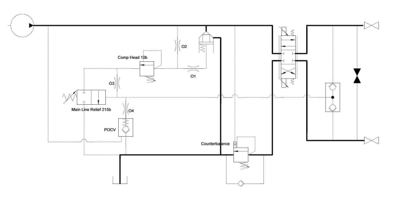
This is right at the opposite end of the complexity and cost scale. The isolation valves on the right hand side supply the rams in a precision motion control application. The application features wide ranging load and speed requirements, but the rams never need to see full pump flow.

You'll see that the proportional valve is closed-centre, so most of the pump delivery has to go through the cartridge valve at the top of the drawing. That valve opens to dump as much of the pump as necessary to restrict the system pressure to the "right" value - "Right" being whatever's coming out of O1.

That pressure can be one of three things.

If the proportional valve is closed, then the entire pump output goes through the cartridge at 10 bar.

When the proportional valve opens, the tapping from the load lines increases the reference pressure, providing a system pressure that drops 10 bar across each edge of the proportional valve, independent of load (which is brilliant if you want a system where flow for a given proportional valve opening is virtually constant). As a final bonus, the main line relief (which is only a diddy little thing) will limit system pressure to 225 bar (though to my mind, it's too complicated an arrangement for you to be able to rely on that feature as a safety relief - I've seen a single component failure on this block push the system pressure up to the point where it blew a hole in the side of the pump).

A.
 
zeusfaber said:
hydraulic schematic

So if I have a 10 GPM gear pump, and I want 7 GPM to the cylinder, what will the pressure be on the pump side of the DCV? Assume no plumbing pressure drops. Say max allowable system pressure set by relief valve is 3000 psi.

Case 1: load pressure = 2500 psi.
Case 2: load pressure = 500 psi.

Repeat for only 2 GPM to the cylinder.
 
Flow will go to the least resistance. Until the cylinder moves, there will be no flow to it. How much pressure is required to get it moving and up to the speed that will take 7 gpm? The operation will be more of crack it open, get the cylinder moving, throttle to keep some speed.

Ted
 
You cant calculate the pressure required for your example numbers because the solution is a complex relationship between the orifice characters and their opening areas. The pump pressure has to be throttled with the open center orifice to a certain pump pressure that let out 7gpm through the work port. Another thing is that you will need higher pressure during acceleration compared to a steady-state 7gpm motion

For your first example, 7GPM to work port of 10GPM pump flow and 2500psi load pressure might even exceed the PRV set at 3000psi. As we noted before the only way to get max pump pressure is to have OC fully closed. which means 10GPM to work port. For sure there will be a pump pressure between 2500psi and 3000psi that will make the 7GPM output but I think will you have to test this live run for a specific directional valve.
I don't think this is of importance in a design situation to know what the pressure needed to be. "It is what it is" in a simple constant flow system. You throttle till you get the speed you need for a certain load. Now you will have another problem if you try to use another actuator that has a totally different load pressure for the remaining 3GPM.
Flow-on-demand constant pressure systems solve a lot of problems. Pressure on-demand in a constant flow system is not that easy.
 
When flow no longer is accepted by the actuator a Pressure Relief Valve, PRV opens. That can be the main pressure relief valve on the pump line or valve inlet or it can be a work port PRV set on lower pressure. Pump flow through the pressure relief valve is 100% converted to heat energy.

This is the key thing. This is what I was curious about. The work port RV set at a lower pressure restricts the pressure the cylinders can get to. So to let the cylinders get to higher pressure, eliminate that and just have the system RV. But then you're dumping over that the whole time during slow movement of the cylinders at a high load pressure. I was ultimately curious about whether that's how it might be designed, with the system RV active the whole time during slow heavy work.
 
You will be metering across both land edges until the flow path to tank is closed or the valve is returned to center position.

Ted
 
Ignore my last post, akkamaan. I think you mean when cylinder deadheads, a RV opens. For some reason, I was taking it to mean when the flow to the cylinder is throttled down.
 
HydraulicGuy said:
But what if the load pressure exceeds the PRV setting?
Then the load won't move

But if you need the stump grinder cylinders to move at some low GPM as you're grinding, and the load pressure is really high, those 2 things (high load pressure and low throttled-down GPM) may be in conflict, right?
There is always a way to throttle that speed if the grinder is the only actuator in action at the moment

The work port RV set at a lower pressure restricts the pressure the cylinders can get to. So to let the cylinders get to higher pressure, eliminate that and just have the system RV.
If the work port doesn't need reduced pressure you can have a port relief at the same pressure or even slightly higher pressure. That to protect the work port circuit from overpressure when the work port is closed. A knuckle boom crane can need a higher setting on the boom than pump PRV. If you extend the boom with a telescope or the arm pressure increases and can cause the boom to drop. Other occasions are when swing or motion inertia comes in to play.
 
Another factor with open center constant flow systems mobile equipment is that we can use the "gas pedal" to vary the pump rpm when using the implements. That can give the operator another "tool" in controlling the actuator speed and the pump flow. Between idling engine rpm (600rpm) and max engine rpm (2000 rpm) we can give the system a wide "flow on-demand" range.
The "matching" of the directional valve vs the most used pump flow is important to give the operator the best control. A valve designed for ideally operating at 20 GPM would not be able to throttle a 10 GPM flow very well since the valve won't build enough pressure until the very end of the valve spool stroke and at that end, the control character will be close to on/off control.
And if we try to push 20 GPM through a valve designed for 10 GPM we will have a high pump pressure built already before the valve spool leaves neutral position and the actuator might overreact when we try to give the actuator a slow speed/low flow.

Another design aspect with the spools in the directional valve is the spool diameter vs the length of spool stroke. A spool design with smaller spool diameter (5/8") will require a longer stroke (1/2") and will, therefore, give the operator better and more proportionality, than a spool design with a bigger spool (7/8") diameter that has a shorter spool stroke (1/4"). To give the higher diameter spools better ability to control lower flower they are given edge notches. Higher diameter spools are preferred in valves they are proportional pilot pressure controlled ie "pilot control joysticks".

So an open center constant flow system in mobile equipment like front loaders, excavators, and logging equipment with loading cranes is most efficient when we run them with variable pump speed.

Today the market of mobile equipment is filled with variable displacement pumps (variable flow systems) that automatically provide flow on demand at a fixed engine rpm. Most mobile equipment also has a hydrostatic drive. These two "properties" work very well together and should both be operated at a fixed rpm, preferably at an rpm just ̶a̶b̶o̶u̶t̶ above where the engine has its peak torque if that rpm can supply sufficient power for the hydraulics So it is not a very good idea to put an open center constant flow system in a piece of mobile with a hydrostatic drive that is operated at fixed rpm.


On mobile power units we sized the pump to allow running the engine above peak torque speed so that increasing load would sag engine speed toward peak torque, not away from it. That prevented overloading and lugging the engine.

Ted
 
Status
Not open for further replies.

Part and Inventory Search

Sponsor