Continue to Site

Eng-Tips is the largest engineering community on the Internet

Intelligent Work Forums for Engineering Professionals

  • Congratulations MintJulep on being selected by the Eng-Tips community for having the most helpful posts in the forums last week. Way to Go!

Excessive inrush and breaker trip during ATS transfer 1

Status
Not open for further replies.

bozic77

Electrical
Oct 12, 2006
5
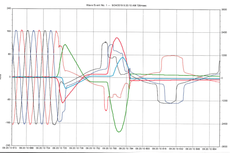
Protection and control building is supplied via 75kVA (208/120V) service via source A (station service transformer stepped from 230 kV line to 208V, 3ph). At few instances, source A dropped and automatic transfer switch (ATS) switches to source B (208V/120V supply by local utility). ATS output feeds AC distribution panelboard which has main 250A breaker. When this condition occurs, main breaker trips. The temporary meter was installed to capture the waveform and there is significant inrush current that appears to be seen by the breaker which causes the trip (around ~1200A). See image below. Any help is appreciated.

aCapture1_stgdhb.png
 
Replies continue below

Recommended for you

Motor loads involved? Cooling pumps/fans perhaps? If so, you may wish to delay the transfer so they have a chance to stop before starting again.
 
i see at least 5 different lines on the graph and two sets of scales, do you have legends?

did the ATS happen around 09:20:10 720?

how do you know this is inrush?
 
Better look again.

MAROON, DarkBLUE, and BLACK are the voltages.

RED, LightBLUE, and GREEN are current.


Those three pedestals rising to '1200A' are NOT current they are voltage rising to only 80V likely after the breaker has tripped.

The current is rising to 2,100A on one phase.
The current is rising to 2,800A on one phase.

Keith Cress
kcress -
 
Transfer switches that make a fast transfer from a generator to the utility do not transfer until the sync check relay sees that they are in phase.
If you are making an out of phase, fast transfer you can expect problems from motors and transformers.
Match your phases between the two sources and try again.
The other issue is that "not so fast" transfers may cause problems even if the sources are in sync.
If your transfer switch does not do a very fast transfer then you may add a time delay to allow the residual back EMFs to die down before re-energizing.
From the graph it looks like a very fast, out of phase transfer.
BUT that depends on how the ATS was switched for the test.
If an outage was simulated by opening an upstream switch then it is a very fast, out of phase transfer.
If the transfer switch was triggered manually with both sources energized it is still an out of phase transfer but we don't know what a graph would look like for an outage. The timing may be different and that will affect the amount of phase difference.
The residual from motors will have a decaying frequency.

Bill
--------------------
"Why not the best?"
Jimmy Carter
 
Sync check is a good point, but OP said ATS transfers to source B when source A is dropped which indicate no need to sync anything? However in the waveforms, it is clear that source A isn't dropped assuming the transfer happened at 09:20:10 720.

Another comment is that we can likely rule out inrush as the cause. Source B(208V/120V supply by local utility) is already energized before the transfer, and besides it is upstream of the panel. Since there is no transformer downstream of the ATS with remnant flux, there shouldn't be any inrush current.
 
A 250 A set at 5 X would trip under these conditions. Like waross said above, add some 'neutral' delay (2-3 sec...) between the break and make.
 
thanks for replies so far.
Voltage Y-axis is left as 160V (LG) before trip. The current is right it it depicts only few amps before the trip. The load on AC board is not major such that there would be an excessive inrush of 1200A. (HVAC unit is about 8kW).

To respond to Warros and Protolash response, I confirmed O&M personnel at P&C building that ATS transfer time set to 15 seconds.

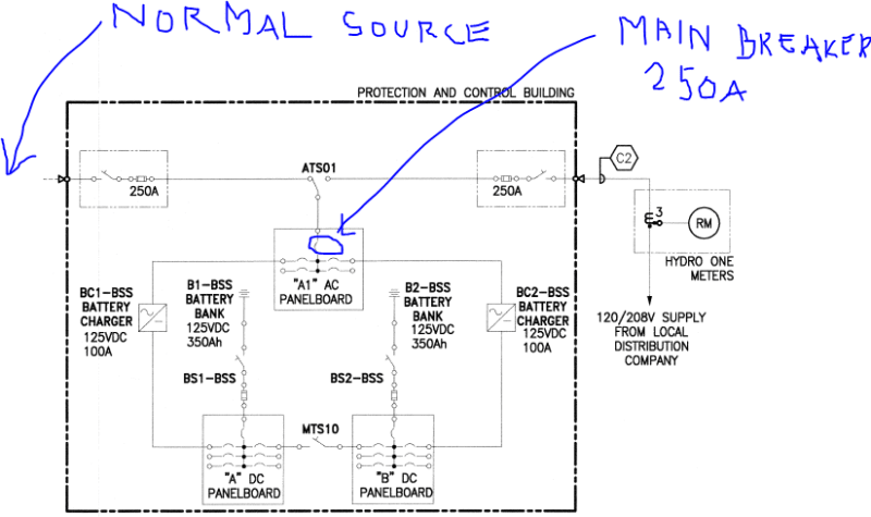
Also, It was confirm temporary meter was placed on lugs of ATS leading towards the main breaker that tripped (See SLD attached).

Further, if phases on alternate source B are not correctly connected to ATS (for example, mixed A/B/C) would this be a potential issue?

AA_pnl_snitbq.png
 
Check that the phases are not rolled between source A and source B.
Inrush current is independant of load.
But not independent of the loads.
Five transformers online will present more inrush to the source than one transformer online.

Bill
--------------------
"Why not the best?"
Jimmy Carter
 
Measure the voltage across each pole of the ATS. It should be close to zero with both sources energized.
There is one type of very fast ATS with no transfer neutral delay possible.

Bill
--------------------
"Why not the best?"
Jimmy Carter
 
In regards to transfer delays.
In a transfer switch there is often no need for a delay to be added to the transfer to backup and often no provision for a delay to be added.
When the main power fails, the generator must start and the voltage must stabilize before the ATS will transfer.
In the majority of cases this is enough time to allow a transfer with no additional time delay added.
If a delay of transfer to backup is needed it may have to be added externally.
When transferring from the backup supply to the normal supply, both sources are live and either a sync check or a time delay is a good idea on all sets and mandatory on many.
Your trace suggests a very fast transfer with no delay and rolled phases between source A and source B.

Look at the first discontinuity on the maroon voltage trace.
At the same instant that the green current starts to rise, the phase voltage also starts to rise and then decays.
This strongly suggests to me that there was an out of phase transfer into a back EMF.
The current surge or transient in this case may be much greater than the normal 6 times locked rotor current.

My very first check would be source to source phasing.
This should be either rectified or ruled out as a possible cause before considering other issues.


Bill
--------------------
"Why not the best?"
Jimmy Carter
 
bozic77; Why do you keep with the incorrect 1200A there is NO 1200A current.

Thanks Bill, I wondered what that maroon discontinuity meant. Fits perfectly with your assessment!

Motors turning backwards after transfer?

Keith Cress
kcress -
 
bozic77 said:
To respond to Warros and Protolash response, I confirmed O&M personnel at P&C building that ATS transfer time set to 15 seconds.

Also, It was confirm temporary meter was placed on lugs of ATS leading towards the main breaker that tripped (See SLD attached).
So all of the currents and voltages were measuring only current and voltage on the load lug of the ATS. With a 15 second transfer time, then the switch was still connected to the normal source. There should be no effect of out of phase transfer because the transfer has not occurred. Seems like the strange voltages are caused by the normal source. What kind of transformer is it? 230 kV - 208 V is unusual. What actually tripped?
 
Same words, different meaning.
The 15 seconds is not shown in the wave form recording.
It may be a 15 second delay before the fast transfer.
It is common to have a 15 second delay before retransfer. If, for instance, a line is closed into a shorted distribution transformer, the re-closers may re-close several times in 15 seconds. Each re-close will reset the 15 second timer. The 15 second delay ensures that the re-closers are not operating. Then there is a fast transfer. This is one mode of operation.
Just because something is set to 15 seconds does not mean that there is a 15 second open circuit delay between source A and source B.
OP said:
Further, if phases on alternate source B are not correctly connected to ATS (for example, mixed A/B/C) would this be a potential issue?
Yes. That's what I have been trying to explain. Should be A-A, B-B, C-C.
A-B, B-C, C-A will give the same rotation but may cause issues on a fast transfer,

No the motors won't be running backwards.
WAG: The back EMF is quite close to the applied voltage. The discontinuity happens on a falling wave form. If the back EMF is lagging, the
instantaneous back EMF may be greater then the applied voltage. Just a guess for discussion.
It looks like an event every 3 cycles. I don't understand that.
Transformer inrush can happen with a step voltage increase at the wrong point on wave. The inrush may be 25 times FLA.
This may be an issue with the battery charger transformers and improper phasing of the sources.

PLEASE VERIFY THAT BOTH SOURCES ARE A-A, B-B, and C-C.

Keith and others: Feel free to speculate.
Can you provide the make and model of the ATS. That will eliminate a lot of speculation.

Bill
--------------------
"Why not the best?"
Jimmy Carter
 
- The issue appears to be on 230kV side; 75kVA transformer is stepped down from 230kV line. Once 230kV breaker trips (due to intentional, planned trip), there is a charge from 230kV underground cable (about 7km long) between two stations; one of the path to the ground is through this unit which causes a surge on the system on 230 kV HV side, reflecting it to LV (208V) side.

- model for the ATS is ASCO 300 Series.

 
Operator's Manual said:
CONTROL FEATURES(continued) IN PHASE MONITOR FOR MOTOR LOAD TRANSFER
In phase monitoring logic controls transfer and retransfer of motor loads, so that inrush currents do not exceed normal starting currents. It avoids nuisance tripping of circuit breakers and mechanical damage to motor couplings.
The Motor Load Transfer feature is built into the controller.
DIP switch S1 (actuator 5) activates this feature: right = ON, left = OFF.
FUNCTIONS 1 DIP SWITCH
enable Actuator 5 on
disable Actuator 5 off
Shaded DIP switches are standard factory setting
The standard factory setting is OFF
This feature is used when transferring from Emergency power to Normal power.

Manual said:
If the transfer to emergency delay is used the transfer should occurs after a time delay(up to 5 minutes).For immediate transfer press the Bypass Time Delay button.
Is this feature activated?The ATCO 300 appears to be a very fast transfer switch. No neutral delay is possible.
Suggestion. If the 230 kV is disconnected at the source, we may be seeing capacitive discharge raising the voltages.
If the cable is ringing it will ring at a frequency dependent on the combined capacitance and induction of the cable.
That would explain the subsequent peak several cycles after the initial event.
Now the puzzle is: What components in the loads will suffer severe current transients with a phase shift in applied voltage.

Bill
--------------------
"Why not the best?"
Jimmy Carter
 
Do the battery charger have transformers ahead of the rectifiers?
A step change in the voltage to a transformer will cause an inrush.

Bill
--------------------
"Why not the best?"
Jimmy Carter
 
Status
Not open for further replies.

Part and Inventory Search

Sponsor