Continue to Site

Eng-Tips is the largest engineering community on the Internet

Intelligent Work Forums for Engineering Professionals

  • Congratulations KootK on being selected by the Eng-Tips community for having the most helpful posts in the forums last week. Way to Go!

Excessive reinforcement in columns 3

Status
Not open for further replies.

Usman3301

Civil/Environmental
Jul 11, 2019
48
Hi there,
I am a junior engineer, currently working on textile mill project and facing an issue, which I haven't been able to resolve for past 3-4 days.
Story heights for textile mill have been shown in images. On Gridlines 17,18,19 and 20, an AC station will be placed and its subsequent loads have been applied on this model. At story - 1, SOG will be placed and therefore restraints in x,y direction have been applied in model.
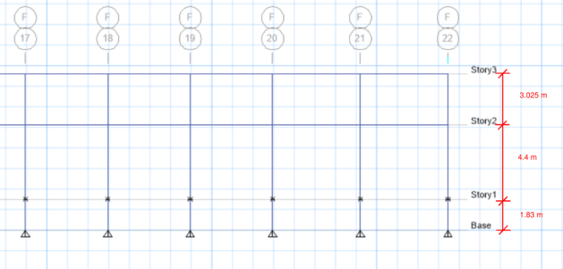
heights_bhdbat.png

When analysis is run and concrete frame design as well, software provides excessive reinforcement at zero points of column against governing gravity load combo. Initially, I thought this maybe due to slenderness effects, but I have checked manually that slenderness doesn't control here. (column size is 21"x21"). Secondly, I thought this might be due to lateral load effects (site is located in zone 2B (Intermediate moment frame)) but gravity load combo ruled out this possibility as well. Also, I have designed column manually against given moments, 24"x24" cross-section will be okay but ETABS model says otherwise. I have run out of ideas and I have to submit design calcs to senior engineer by tomorrow. Kindly help me out in this and assist me in understanding why I am getting these values.

3D MODEL:
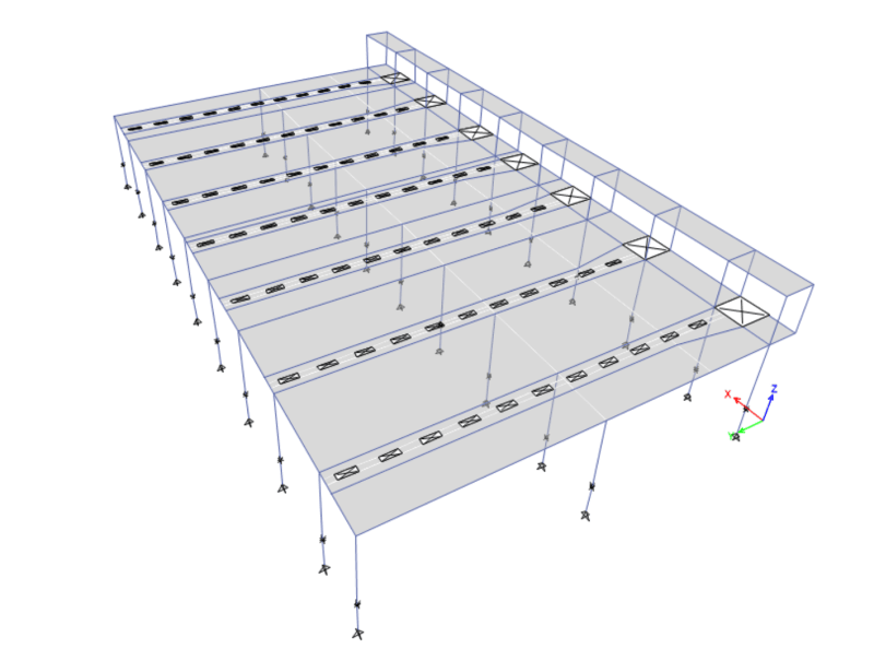
3d_oxthhy.png


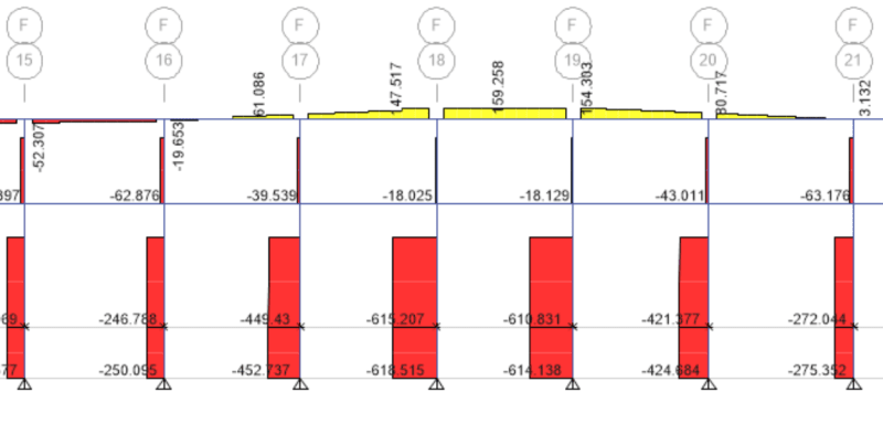
AXIAL FORCES IN COLUMNS
AXIAL_FORCE_jzf7wk.png


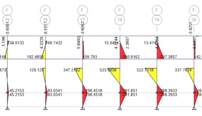
GOVERNING MOMENTS IN COLUMNS
MOMENT2-2_nt5fqc.png


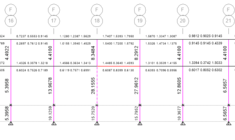
COLUMN REINFORCEMENT (unit - in^2)
REINFORCEMENT_gizzdx.png


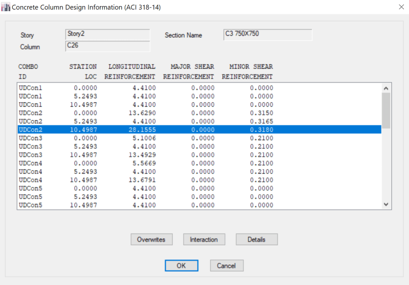
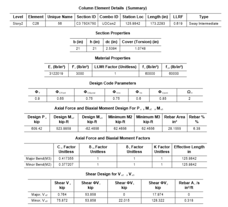
COLUMN DESIGN DETAILS (GRID F-18)
REINFORCEMENT-2_pg4z8z.png

REINFORCEMENT-3_nx9dkq.png


Replies continue below

Recommended for you

Those are extremely high axial loads for a 2 story structure. Those are akin to 6 story buildings. Are you sure you used the correct units for loading? It seems like you're mixing up imperial and metric units. How could the axial loading change from 18 kips to 611 kips over one floor? Is it due to industrial equipment? The equipment there would have to be at least 600 kips heavy, which is equal to a solid block of steel that's 12'x12'x8.33', assuming it's right next to the column.

The shears on the columns are also extremely high. I don't think the worst earthquake in the world would produce shears that large. There seems to be something wrong in the loading here. The moments are also really high and would need to be specifically analyzed for the moment connection between the beam and column.

I'd also check stiffness factors for columns and beams. This will change the distribution of moments since the real moment of inertia of a 24"x24" column is much less than the standard rectangle equation. It's based on the compression stress block and tension bars rather than the gross area. I believe beams use 0.35 x I and columns use 0.7 x I, but you should check your code.

Anyway, the best way to resolve this is to use hand calculations. Use ETABS for analysis of forces and stiffness only. Lots of engineers do that. I personally never use ETABS for concrete design calculations, and especially columns; something about it is just wrong and doesn't match hand calculations. If it's still not working out, just don't use ETABS at all, and calculate the worst case by hand. It's hard to figure out a mistake in the software file when a senior engineer doesn't look at it.
 
@milkshakelake Thanks for your valuable input.

milkshakelake said:
[How could the axial loading change from 18 kips to 611 kips over one floor?]

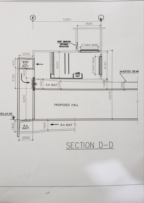
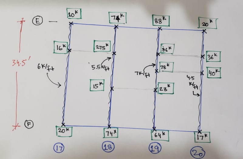
You are quite right in your reservation regarding excessive axial load. There are two rotary filters placed on the story - 2 , and their cumulative weight along with wall loads and floor finishes etc, equates to around 1500 kips. Which justifies excessive axial loads on these columns. An image has been attached for better understanding. (Loads of rotary filters and other miscellaneous loads from above story have been applied on Inverted beams directly). Also, there are ducts which 4' wide and 5' in height. All these loads have been checked and applied properly.

20210516_213612_rsqs6l.jpg


Applied loads
20210516_2153161_cssbkn.jpg


I have also assigned stiffness modifiers as per ACI 318-14, 0.35 Ig = Beams, and 0.7 Ig = columns

 
Maybe the ETABS result is trying to tell you that you need more columns under the heavy equipment.
 
@SWComposites
Thing is, when columns are designed based on ETABS output (Moment and Axial force) manually, I don't have to provide so much reinforcement (As =29 in^2 as reported by ETABS is way too much for even this load). I am interested in finding out why ETABS output, especially at beam-column joint is way too excessive! Is it that I am missing something or as "Milkshakelake" has suggested, it's better to design manually.
 
@Usman3301 If all the loading is correct and checked, 6.38% rebar is too much for a 21"x21" column. It is allowed by code but gets congested in field when pouring concrete. It can lead to voids in the concrete, which I've seen even for 2% reinforced columns when concrete is poured too fast. It's not a good thing when you have 1500 kip equipment; you want to be extra careful in this case. It will also lead to problems in splices when pouring columns for the roof.

The 76 kip shear at grade can also be a problem, and not something I'd trust to an unreinforced slab on grade.

Since slenderness is not an issue, the way to deal with the column reinforcement is to use moment and axial interaction (P-M interaction) like in Design of Concrete Structures by Nilson (14th ed) page 270 for short columns. This can take days to make though, and doesn't fit your time frame. You can also try to use spColumn, which gives more accurate designs than ETABS. If you want a quick solution, maybe make the columns longer in the major axis and it will be satisfied in ETABS. Lastly, make sure that your ETABS is legal. The pirated version tends to overdesign things on purpose.
 
I'm relatively young (EDIT - depends on who you ask lol) so it may be a surprise that outside of university I have never fired up a modelling software for analysis. I use all kinds of software: AutoCad for 2D shoring details, Solidworks for Shop DWGs, python/R/C++ programs for typical designs I've coded, etc. However, I find FEM and other analysis programs kind of a catch 22 situation. I won't trust them (nor am I allowed to per my association's code of ethics) until I've verified them by some other means, which means roughly approximated by hand. But if I have to do the hand calculation anyway what was the benefit of the program? To make me marginally more confident in a lighter design? No thanks.

Your path is clear.

Step 1: Calculate the loads by hand and see if they match (approximately) with your model
Step 2: If loads match proceed to step 3. If loads do not match stay at step 1 until you figure out why.
Step 3: Design the members by hand. If design does not match program stay at step 3 until you find out why.
Step 4: If step 3 is not fruitful and disagreements persists see what other designs are available from your office for similar loading. Compare the designs produced by hand vs computer output and use older designs from the office to corroborate one, the other, or none.
Step 5: If any doubt is left overdesign and get a senior engineer to review.
 
A couple of thoughts:

I agree that the assumption that the slab-on-grade will sufficiently suck up all the shear without fail is pretty dicey when your shears get this big. Just because you can model it this way doesn't mean the building will act this way. When the contractor puts in 1/2" isolation joint material around the columns before he pours the slab, it will change your moment distribution significantly when the joint material compresses.

The UBC hasn't been updated in over 20 years. I'm not sure why anyone would use "Zone 2B" any more. The material codes are now written for the current model codes, not the old UBC. Mixing the two might not be appropriate. It seems to me that the UBC Seismic Zone 2B zone created for Memphis in an effort to pretend their seismic issues didn't really exist and that they could get away with minimal special detailing.

Maybe your biaxial bending is what is killing you. You will have large gravity moments in one direction with full seismic moments in the other. Also, don't forget to combine the seismic loads in two directions where required.
 
Status
Not open for further replies.

Part and Inventory Search

Sponsor