michaelwoodcoc
Automotive
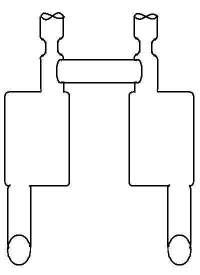
Hey guys & gals of the ENG-TIPS forums! I've been working trying my hand at finding good exhaust drone cancelation solutions, because I'm trying to further my understanding of sound waves and automotive engineering. I work in R&D, and I took a project on for someone who bought an aftermarket exhaust and immediately had a huge drone! Some back drop:
2017 Camaro SS V8
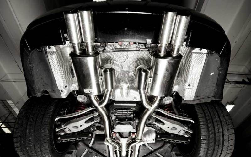
Legato performance exhaust
Originally the exhaust was so bad it would shake the whole car, causing the whole body to vibrate and really hurt your ears. Anyways. My co-worker who speaks english as a second language already typed up a report, which I'll post below. I am looking for additional solutions as we want to completely resolve this issue. I have a few in mind, but more on those after the report.
REPORT:
Due to the replacement of aftermarket mufflers, the crew is suffering from an intensive acoustic drone throughout each gear between 1500 to 2500 RPM under medium to high engine load. In order to reduce this effect, several methods were tested.
Original exhaust sound data logging
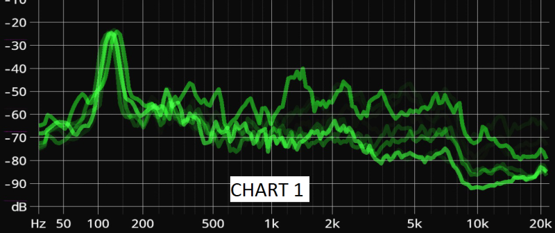
With several test drive we are able to collect the data and visualize the sound wave. The overlay of the sound wave file (chart1) indicates that there is very strong peak between 120 to 150Hz at
about -25 to -22 Db with a strong noise level across between 200 and 7500Hz. Based on the theory of the most common range for human hearing is around 1000Hz. Therefore, we made our assumption that we should aiming to lower the noise around the 1000Hz area while focused reducing the 120~150Hz range.
Collecting more information
With the known value of the noise inside cabin, we decided to test the resonating frequency of the exhaust pipe and trunk. The reason we did this is because
1, we are trying to find out if the drone is originally generated from the engine firing order or the resonance of the exhaust pipe.
2, the trunk space (as well as the dual layer trunk lid) are acting as an acoustical chamber that amplifiers the exhaust noise.
Based on the testing we find out that the resonating frequency of the trunk lid is around 220hz and the exhaust pipe is around 120Hz.
Exhaust J pipe
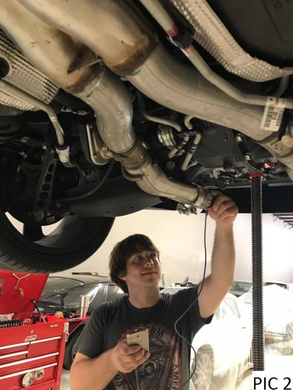
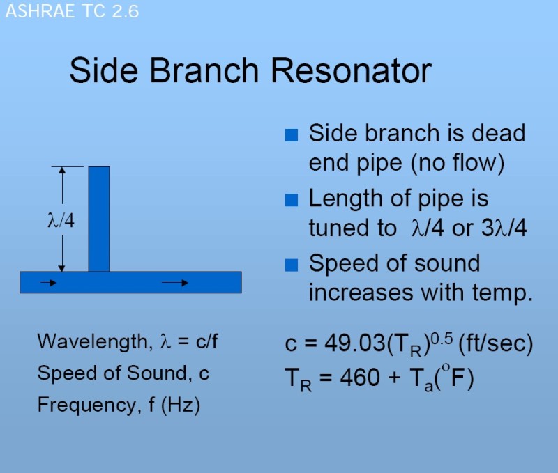
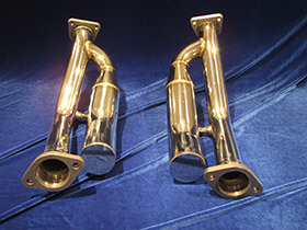
The first step we utilize is to create an acoustical pass the run along the exhaust pipe before the mufflers. These acoustic passes are also referred as the J pipe to the public due to its shape. The theory behind this device is to use the pausing wave from the original exhaust flow to travel a certain distance and bounce back to the main exhaust gas flow to cancel the original exhaust sound wave. In theory this method will work but it does have its own draw backs, the length of the path has to be calculated and the ideal length can only cancel the noise at certain Hz but not across the wide range. At this point we invited a sound engineer to help us doing the analysis and decided to focus the targeting frequency range to 120Hz and based on the calculation, we generated our target path length should land at 27.5 inch length.
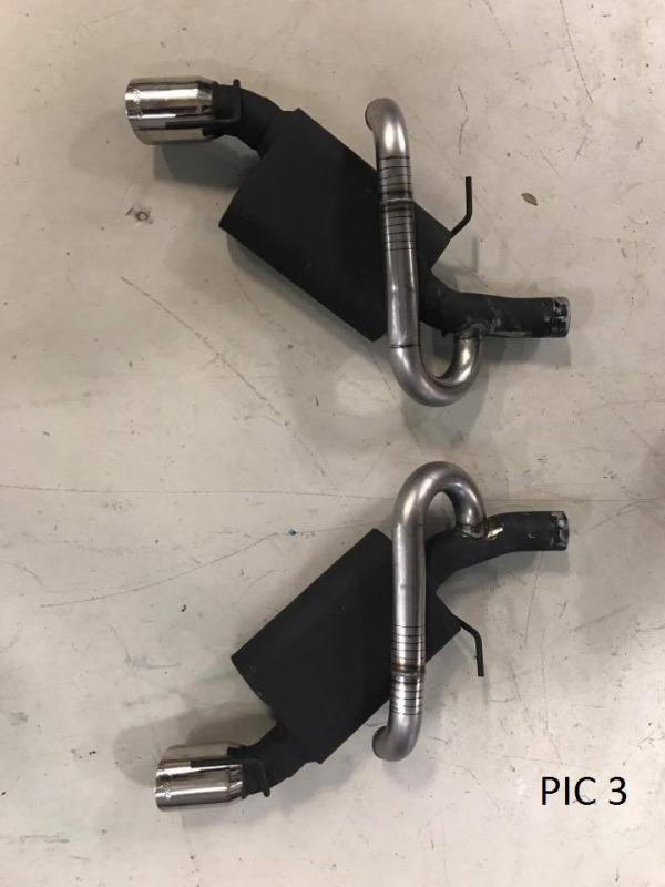
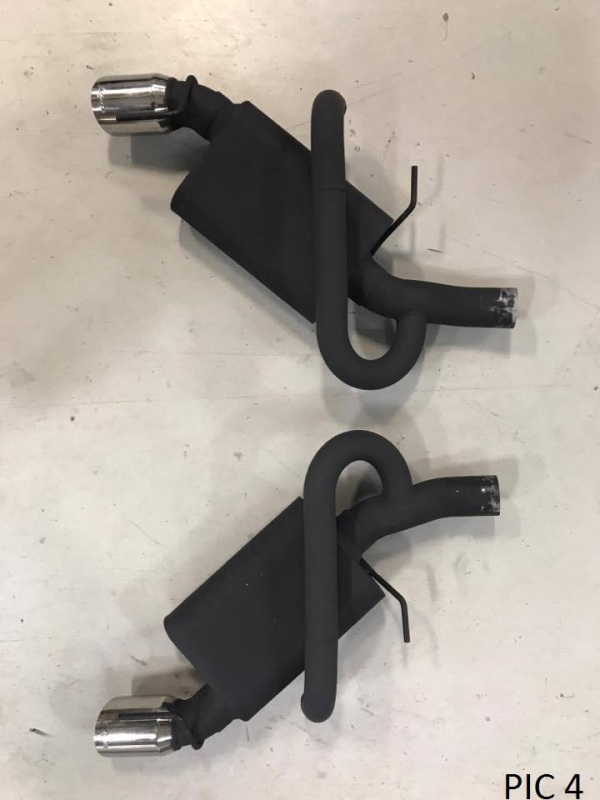
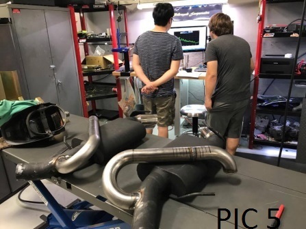
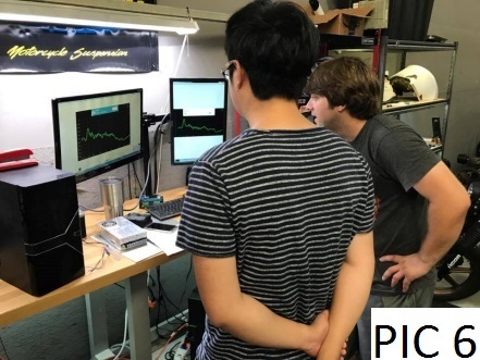
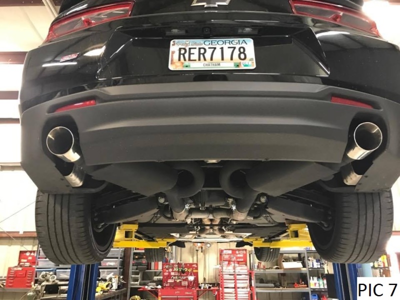
We perfoemced several testing after the Jpipe installed with the length around 28 inch and finally confirmed the 27.5 inch provided the best result for this application.
Chart 2 reveals the different results that different length pipe creates.we notice that the J pipe effect not only reduced certain frequency but also boost the level of other frequencies as well. Therefore, we are trying to find out the most balanced point (27.5inch) and to further reduce the niose by apply sound deadening material.
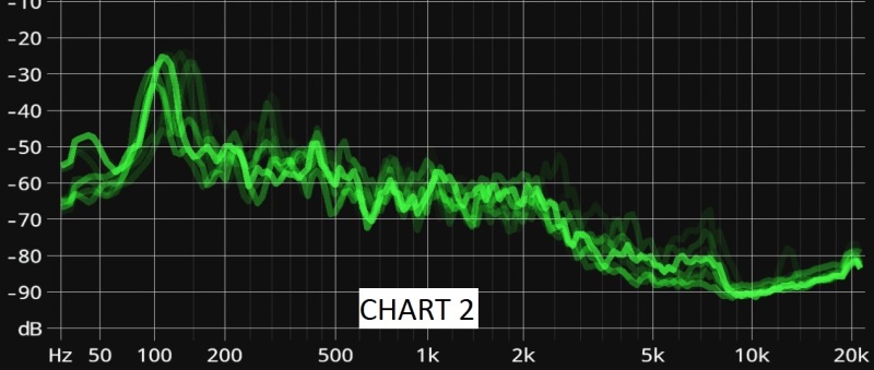 CHART 2
Sound dedening installed with exhaust servo disconnected
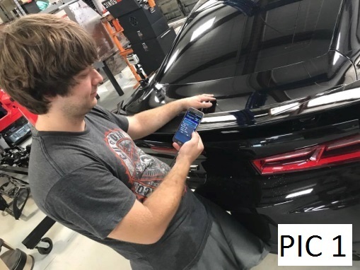
With the sound deadening material applied to the trunk area, we did the test again with the exhaust servo disconnected (constantly open position) in order to eliminate all the potential varieties the ECU controlled servo will provide. Then we got a testing result like this (Chart 3).
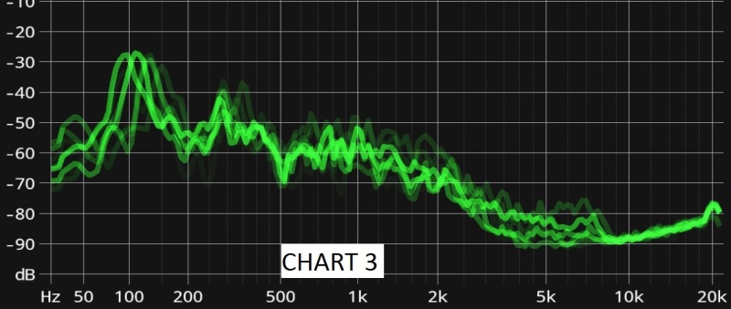
CHART 3
It is worth to point out that at although the chart shows the sound wave in quite similar shape as before, we were actually trying to hunt this peak level by porously loads the engine in a very low RPM range, and we barely got any drone through the 1-5th gear (7 gears total). However, according to chart 3, although the low frequency level reduced to around -30Db, the noise across the whole range actually goes up. This was within our expectation that the exhaust servo was put on from factory for noise reduction propose. Therefor we reconnected the servo and did the test again and get the result like this (chart 4)
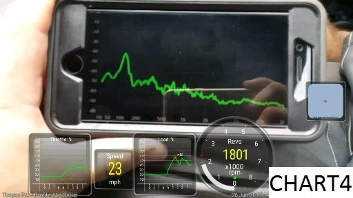
CHART 4
Chart 4
Now, it is very clearly to see with the servo connected, the noise level reduces dramatically across the whole range. The peak at around 100Hz reaches lower than -40Hz level, and the most sensitive area (around 1000hz) is dramatically reduced to under -70Hz. Please be note that this is the freeze screen on the low speed, 7th gear, and the highest engine load condition.
Weighting the exhaust system
With the already great result, we are trying to test if we can achieve an even better result by put extra weight on the exhaust in order to reduce the vibration resonance of the exhaust system itself. We put 5 pounds weight at the very end of the exhaust system and did the test again. However, the noise level actually boosted instead of reduced. We can see the value from chart 4
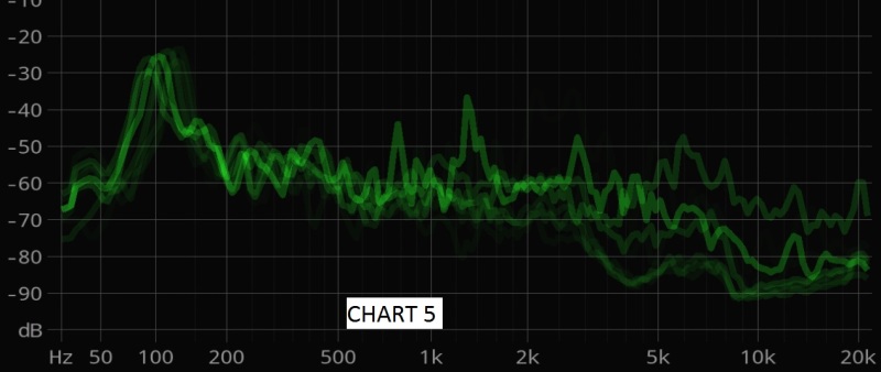
CHART 5
Extra weight would seem impractical. It seemed to make the drone happen at a lower RPM.
END OF REPORT
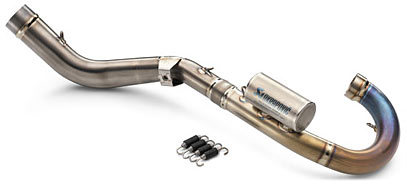
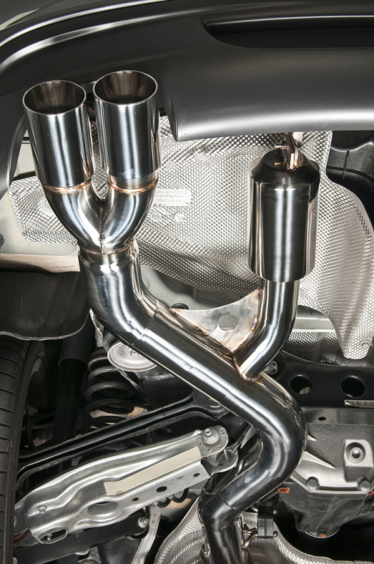
We are evaluating resonant chamber designs, and other possible changes to reduce the drone. The muffler kit seems to use chambered exhausts. if these are designed improperly will they produduce this problem?
2017 Camaro SS V8
Legato performance exhaust
Originally the exhaust was so bad it would shake the whole car, causing the whole body to vibrate and really hurt your ears. Anyways. My co-worker who speaks english as a second language already typed up a report, which I'll post below. I am looking for additional solutions as we want to completely resolve this issue. I have a few in mind, but more on those after the report.
REPORT:
Due to the replacement of aftermarket mufflers, the crew is suffering from an intensive acoustic drone throughout each gear between 1500 to 2500 RPM under medium to high engine load. In order to reduce this effect, several methods were tested.
Original exhaust sound data logging
With several test drive we are able to collect the data and visualize the sound wave. The overlay of the sound wave file (chart1) indicates that there is very strong peak between 120 to 150Hz at
about -25 to -22 Db with a strong noise level across between 200 and 7500Hz. Based on the theory of the most common range for human hearing is around 1000Hz. Therefore, we made our assumption that we should aiming to lower the noise around the 1000Hz area while focused reducing the 120~150Hz range.

Collecting more information
With the known value of the noise inside cabin, we decided to test the resonating frequency of the exhaust pipe and trunk. The reason we did this is because
1, we are trying to find out if the drone is originally generated from the engine firing order or the resonance of the exhaust pipe.
2, the trunk space (as well as the dual layer trunk lid) are acting as an acoustical chamber that amplifiers the exhaust noise.
Based on the testing we find out that the resonating frequency of the trunk lid is around 220hz and the exhaust pipe is around 120Hz.
Exhaust J pipe


The first step we utilize is to create an acoustical pass the run along the exhaust pipe before the mufflers. These acoustic passes are also referred as the J pipe to the public due to its shape. The theory behind this device is to use the pausing wave from the original exhaust flow to travel a certain distance and bounce back to the main exhaust gas flow to cancel the original exhaust sound wave. In theory this method will work but it does have its own draw backs, the length of the path has to be calculated and the ideal length can only cancel the noise at certain Hz but not across the wide range. At this point we invited a sound engineer to help us doing the analysis and decided to focus the targeting frequency range to 120Hz and based on the calculation, we generated our target path length should land at 27.5 inch length.


We perfoemced several testing after the Jpipe installed with the length around 28 inch and finally confirmed the 27.5 inch provided the best result for this application.
Chart 2 reveals the different results that different length pipe creates.we notice that the J pipe effect not only reduced certain frequency but also boost the level of other frequencies as well. Therefore, we are trying to find out the most balanced point (27.5inch) and to further reduce the niose by apply sound deadening material.

Sound dedening installed with exhaust servo disconnected
With the sound deadening material applied to the trunk area, we did the test again with the exhaust servo disconnected (constantly open position) in order to eliminate all the potential varieties the ECU controlled servo will provide. Then we got a testing result like this (Chart 3).

CHART 3
It is worth to point out that at although the chart shows the sound wave in quite similar shape as before, we were actually trying to hunt this peak level by porously loads the engine in a very low RPM range, and we barely got any drone through the 1-5th gear (7 gears total). However, according to chart 3, although the low frequency level reduced to around -30Db, the noise across the whole range actually goes up. This was within our expectation that the exhaust servo was put on from factory for noise reduction propose. Therefor we reconnected the servo and did the test again and get the result like this (chart 4)

CHART 4
Chart 4
Now, it is very clearly to see with the servo connected, the noise level reduces dramatically across the whole range. The peak at around 100Hz reaches lower than -40Hz level, and the most sensitive area (around 1000hz) is dramatically reduced to under -70Hz. Please be note that this is the freeze screen on the low speed, 7th gear, and the highest engine load condition.
Weighting the exhaust system
With the already great result, we are trying to test if we can achieve an even better result by put extra weight on the exhaust in order to reduce the vibration resonance of the exhaust system itself. We put 5 pounds weight at the very end of the exhaust system and did the test again. However, the noise level actually boosted instead of reduced. We can see the value from chart 4

CHART 5
Extra weight would seem impractical. It seemed to make the drone happen at a lower RPM.
END OF REPORT
We are evaluating resonant chamber designs, and other possible changes to reduce the drone. The muffler kit seems to use chambered exhausts. if these are designed improperly will they produduce this problem?


![[glasses] [glasses] [glasses]](/data/assets/smilies/glasses.gif)
