MacMcMacmac
Aerospace
Good Day. Here is a rather long-winded explanation of my issue, and a request for assistance if you have a spare few minutes.
We have had a failure on our 2MW exhauster set. Last year, we spent quite a lot of time and money getting one of our 1350hp motors on this unit to within acceptable vibration levels. Unfortunately, during our annual maintenance shutdown, it has been discovered that the twin to it has a 50% resistance imbalance on one of the wound rotor windings. I can hear the crane loading the motor as I type this. What is even more unfortunate, its that we are smack dab in the middle of a very important test campaign, and we were relying on this exhauster set to allow us to reach the altitude points requested by the client.
There is a second machine in our facility which will allow us to reach a majority of the test points. It is a 5MW compressor/exhauster. Right now, it is set up the same as the 2MW machine: a low pressure stage exhausts into a pipe, which passes the air through an intercooler into a "high" pressure stage which discharges to atmosphere.
As it is configured right now, the 5MW machine is rated for 24,000cfm and 100 psia. The first stage on the 2MW machine is rated at 1250m3/min, or roughly 44000cfm. Obviously, the 5MW will flow nowhere near the 2MW first stage, so it is natural it cannot achieve the same altitude settings once flow through the test rig exceeds its capacity.
There is an option open however. The 5MW machine as delivered and installed, had the capability of being configured to flow in a "parallel mode" of operation whereby both stages of the compressor/exhauster could be exposed to the same inlet pipe, and both discharge to the same stack. A second inlet valve to the second stage and a second discharge valve from the first stage were opened, and the path through the intercooler was isolated. In this mode, we essentially give up pressure capability for a much greater flow capability.
What I am wondering is, would two LP stages acting in parallel have the capability of producing the same vacuum levels as the 2MW in a LP/HP staged configuration. I know from my years of working with compressors that higher pressures necessitate staging, and since the 5MW would essentially be turned into a single stage, high flow, low pressure compressor, how much vacuum potential would I be giving up?
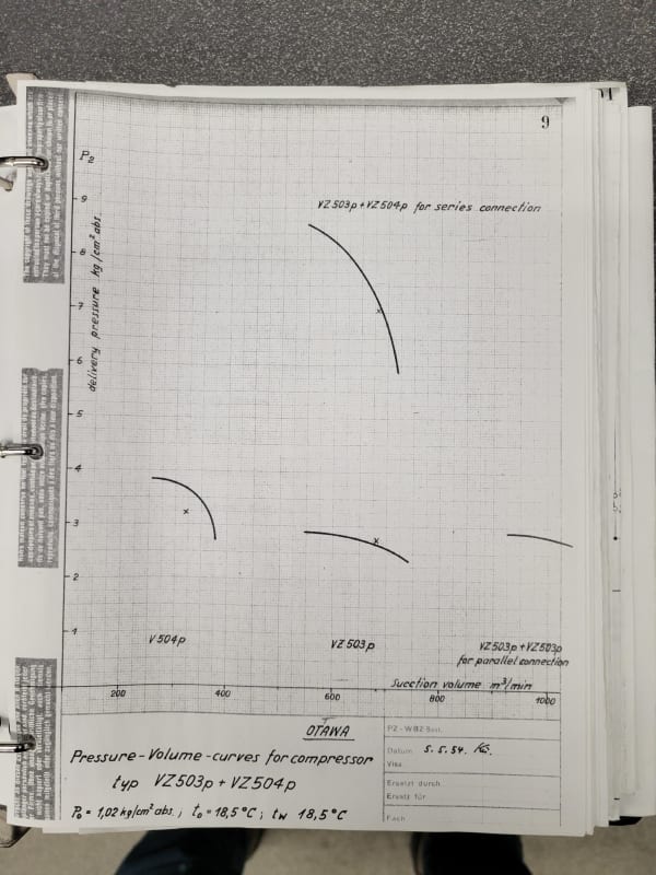
The 2MW LP stage is rated at 1250m3/min (44000cfm), discharging into a HP stage rated at 403 m3/min (14000cfm). 1st stage discharge rating is 4.4psia, 2nd stage is 15psia, if I am reading the 1930's era German language tags correctly. We have virtually no literature on this machine, but curiously, I have the performance curves from the 1930s.
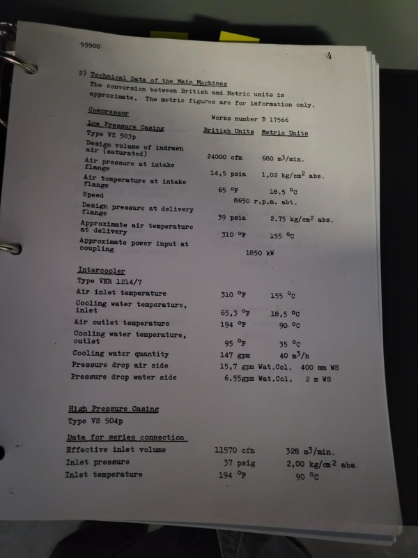
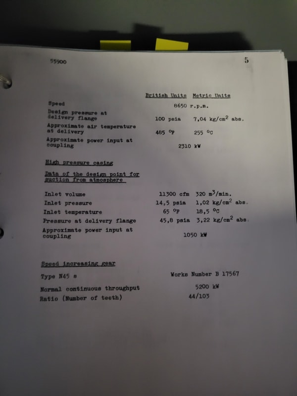
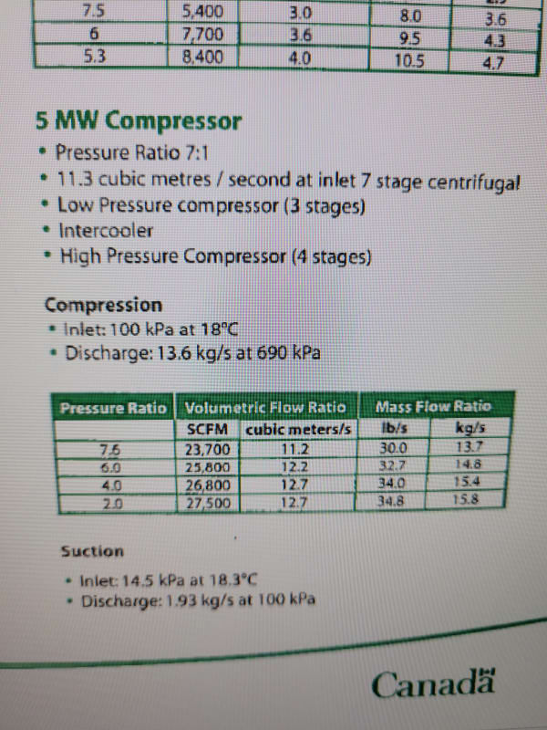
The 5MW LP stage is rated at 24,000cfm, the HP stage is rated at 11,300cfm when pulling from atmosphere in parallel mode. The LP stage is rated at 39psia discharge from 14.5psia inlet, the HP stage rated at 45psia discharge from 14.5psia inlet. Together, they still do not quite equal the flow rate of the 2MW first stage, but it is still considerably better than the 5MW configured in a 2 stage arrangement.
Since the pressure ratios of the 5MW compressor even in parallel mode are much higher than the 2MW stages, I am thinking we are not losing much vacuum potential, if any, since the 2MW stages are rated much lower in the pressure domain. This makes sense, since the size of the 2MW air ends are quite large compared to their motors, and easily over-amp the motors if inlet valve settings are too aggressive. The 5MW on the other hand, is a largely set-and-forget machine which rarely exceeds a 1MW draw no matter what condition we are at.
Unfortunately, the parallel mode was nullified a few years ago when the second discharge valve from the 1st stage was removed due to corrosion and the fact that it had never ever been used in that mode.
The restoration of this option would require some minimal piping mods and the installation of a new valve. I am hoping that I can make the case, and if it turns out to meet our requirements going forward, it would give us 100% redundancy in case of another 2MW unit failure, or we might even consider retiring the 2MW unit completely, which I am fully in favour of since the failure rate of this machine seems unacceptable. I think we are on the back end of the bathtub curve with this machine. I have compiled a list of multi-stage exhauster manufactures and brochures on the network as a major hint.
The only thing that concerns me, is that the 5MW will surge at around 39,000ft of simulated altitude, whereas the 2MW will proceed up past 60,000ft before entering the surge zone. The current test seems to require test points just outside the current flow capacity of the 5MW as configured.
Thanks for reading this far. If you need clarification on anything let me know. As always, I appreciate any guidance.
We have had a failure on our 2MW exhauster set. Last year, we spent quite a lot of time and money getting one of our 1350hp motors on this unit to within acceptable vibration levels. Unfortunately, during our annual maintenance shutdown, it has been discovered that the twin to it has a 50% resistance imbalance on one of the wound rotor windings. I can hear the crane loading the motor as I type this. What is even more unfortunate, its that we are smack dab in the middle of a very important test campaign, and we were relying on this exhauster set to allow us to reach the altitude points requested by the client.
There is a second machine in our facility which will allow us to reach a majority of the test points. It is a 5MW compressor/exhauster. Right now, it is set up the same as the 2MW machine: a low pressure stage exhausts into a pipe, which passes the air through an intercooler into a "high" pressure stage which discharges to atmosphere.
As it is configured right now, the 5MW machine is rated for 24,000cfm and 100 psia. The first stage on the 2MW machine is rated at 1250m3/min, or roughly 44000cfm. Obviously, the 5MW will flow nowhere near the 2MW first stage, so it is natural it cannot achieve the same altitude settings once flow through the test rig exceeds its capacity.
There is an option open however. The 5MW machine as delivered and installed, had the capability of being configured to flow in a "parallel mode" of operation whereby both stages of the compressor/exhauster could be exposed to the same inlet pipe, and both discharge to the same stack. A second inlet valve to the second stage and a second discharge valve from the first stage were opened, and the path through the intercooler was isolated. In this mode, we essentially give up pressure capability for a much greater flow capability.
What I am wondering is, would two LP stages acting in parallel have the capability of producing the same vacuum levels as the 2MW in a LP/HP staged configuration. I know from my years of working with compressors that higher pressures necessitate staging, and since the 5MW would essentially be turned into a single stage, high flow, low pressure compressor, how much vacuum potential would I be giving up?
The 2MW LP stage is rated at 1250m3/min (44000cfm), discharging into a HP stage rated at 403 m3/min (14000cfm). 1st stage discharge rating is 4.4psia, 2nd stage is 15psia, if I am reading the 1930's era German language tags correctly. We have virtually no literature on this machine, but curiously, I have the performance curves from the 1930s.
The 5MW LP stage is rated at 24,000cfm, the HP stage is rated at 11,300cfm when pulling from atmosphere in parallel mode. The LP stage is rated at 39psia discharge from 14.5psia inlet, the HP stage rated at 45psia discharge from 14.5psia inlet. Together, they still do not quite equal the flow rate of the 2MW first stage, but it is still considerably better than the 5MW configured in a 2 stage arrangement.
Since the pressure ratios of the 5MW compressor even in parallel mode are much higher than the 2MW stages, I am thinking we are not losing much vacuum potential, if any, since the 2MW stages are rated much lower in the pressure domain. This makes sense, since the size of the 2MW air ends are quite large compared to their motors, and easily over-amp the motors if inlet valve settings are too aggressive. The 5MW on the other hand, is a largely set-and-forget machine which rarely exceeds a 1MW draw no matter what condition we are at.
Unfortunately, the parallel mode was nullified a few years ago when the second discharge valve from the 1st stage was removed due to corrosion and the fact that it had never ever been used in that mode.
The restoration of this option would require some minimal piping mods and the installation of a new valve. I am hoping that I can make the case, and if it turns out to meet our requirements going forward, it would give us 100% redundancy in case of another 2MW unit failure, or we might even consider retiring the 2MW unit completely, which I am fully in favour of since the failure rate of this machine seems unacceptable. I think we are on the back end of the bathtub curve with this machine. I have compiled a list of multi-stage exhauster manufactures and brochures on the network as a major hint.
The only thing that concerns me, is that the 5MW will surge at around 39,000ft of simulated altitude, whereas the 2MW will proceed up past 60,000ft before entering the surge zone. The current test seems to require test points just outside the current flow capacity of the 5MW as configured.
Thanks for reading this far. If you need clarification on anything let me know. As always, I appreciate any guidance.