Eng-Tips is the largest engineering community on the Internet

Intelligent Work Forums for Engineering Professionals

Existing steel beam - cutting part of it off near the support 1

Status
Not open for further replies.

greznik91

Structural
Feb 14, 2017
186
0
0
SI
Hi,

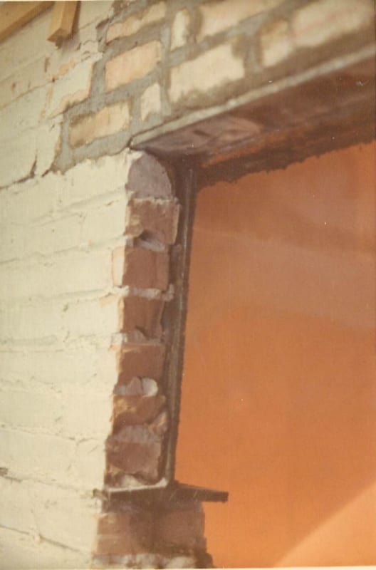
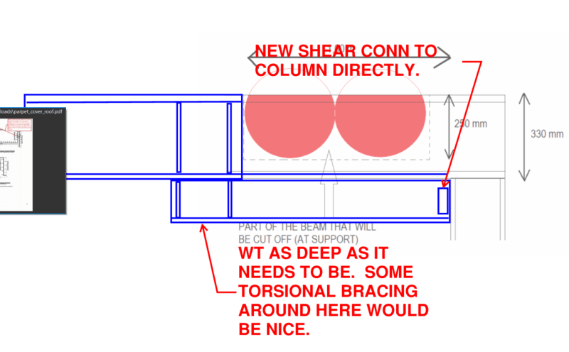
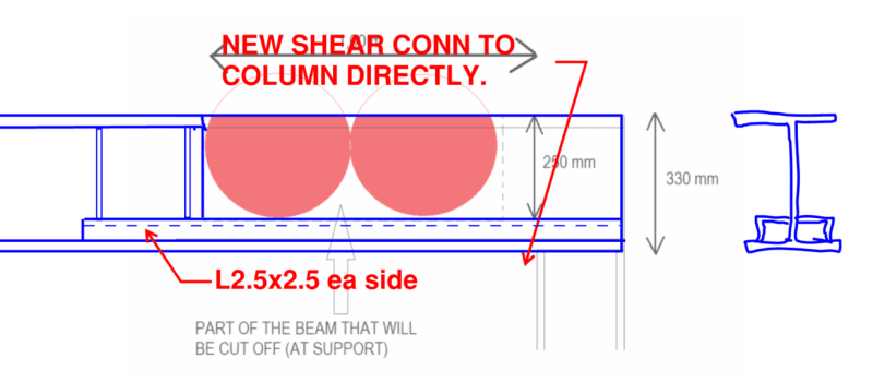
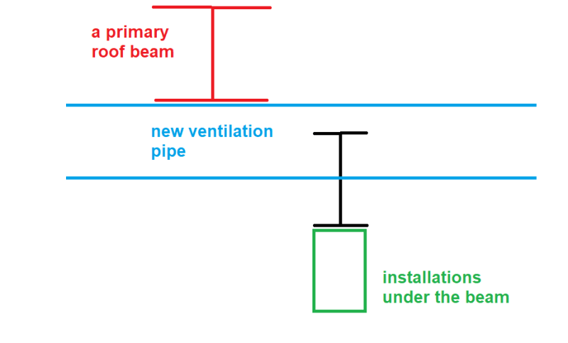
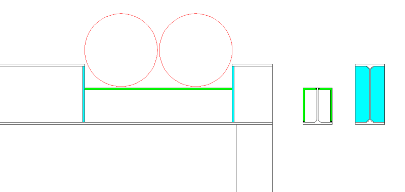
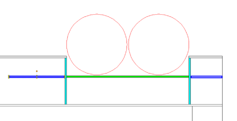
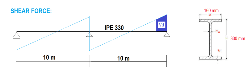
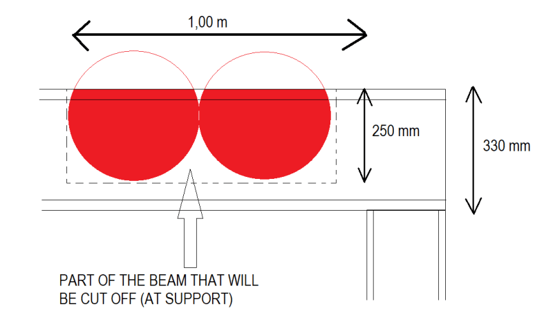
How would you strenghten a steel beam near the support after cutting half of it off (as shown in image)?
The beam is continuous (10 m span) and it is only loaded with self weight and some installations (1 kN/m).
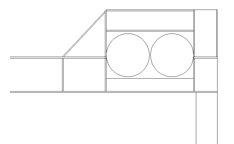
The contractor wants to install some new ventilation pipes that will go through existing steel beam near
the support where shear forces are the largest. How would you strenghten/reinforce it? What would you suggest?

Thanks.


q2_zb8fki.png


q1_pahtk3.png
 
Replies continue below

Recommended for you

You can design for it if your loads are light and shear isn't a big issue, else, you might have to introduce a support of some kind. It's generally not a really good idea to cut off such a large part of the beam.

I had a project several decades back where they were putting in a new door opening to a basement. It was an old steel framed building with brick infill. I created a strip footing to support the masonry and changed it to a brick bearing wall by cutting out the bottom flange and entire web of w WF24. Looked wierd... contractor was a little concerned and moreso when I told him to make sure he wore a hardhat. It was an 8 or 10 storey building.

Clipboard01_fuhybl.jpg


Rather than think climate change and the corona virus as science, think of it as the wrath of God. Do you feel any better?

-Dik
 

My opinion is , it is not a good idea to cut the web and top flange around the support which shear is max. I will suggest, reject this kind of alterations which would compromise the structural behavior . What is your position for this existing str. project ? Did you design the bld. ? . You may consider to shift the location around the midspan with rectangular ducts which need only web openings.

I attached the SCI publication .

EDIT:Only IPE 360X130 self weight 0.5 kN/m. Total UDL 1.0 kN/m seems low. I suspect regarding the conn. of the beam to the column ( second picture ) if rigid or semi- rigid. Can you post more details ( the structural plan, conn. etc..)
 
 https://files.engineering.com/getfile.aspx?folder=69884f6a-54c1-42d9-af99-01e7085014df&file=SCI_P355-design_of_composite_beams_with_web_opennings.pdf
greznik91 said:
What would you suggest?

Find a different spot for the ventilation. Or have the MEP engineer run calcs to determine how large of a hole can be cut in the duct to allow the beam to run through it - that's about as plausible as the initial suggestion.
 
KootK: I was thinking similarly but then I thought if headroom isn't an issue to put a beam below why couldn't the ducts be run underneath themselves (it's for a vent so slope isn't an issue)?

This seems like one of those times you say no and see what happens. Sometimes if you say no enough the mechanical guys figure out something different.
 
Enable said:
I was thinking similarly but then I thought if headroom isn't an issue to put a beam below why couldn't the ducts be run underneath themselves (it's for a vent so slope isn't an issue)?

That may well be the case and I had considered it. That said, I really see few other options short of just not having the ducts there. And it's hard to know what OP's constraints are until he elaborates upon them. Maybe they just don't want to have to drop the ducts locally and bring 'em up afterwards, who knows. Given the load involved, it's also entirely possible that this, or something like it, could be worked out with something as shallow as a 3" HSS. Perhaps a 3" headroom compromise would be possible whereas a 12" headroom compromise for the duct would not have been.

I like to see multiple options brought to the table in threads like this. "Don't put the openings there" may well be the right answer but I doubt that it's one that didn't occur to OP prior to initiating this thread.
 
Perhaps I'm just too sensitive to this right now. Had a remarkably similar situation in a wood building. They wanted to rout a duct in effectively the same place but would have to cut an existing wood beam to do it. I said no, we can shift the duct to midspan, alter the shape and pass through the beam at a point where we can reinforce it. Mechanical hacked the hole where they wanted anyway and then told me to fix it. So I said no, move the duct and we'll replace the beam you just destroyed. They were shocked to find out I had been serious...

So I agree that KootK's option may work it if it meets all other constraints. If you have to stay within the existing beam depth, it would be harder.

I did the conversion...you're cutting about 10" out of a 13" beam with a shear force of about 860lbs. You may be able to cut it out and just slap a new "top flange" on it that runs back a foot or so into the web and a vertical stiffener or two, but you'll need to carefully consider the effects on whatever is installed above.
 
Replace that section plus 3 feet on either side with a beam large enough so the ducts go through the web? Include a web stiffener between and on both sides of the ducts. Notch the new taller beam at the column, box it in and weld it up. Splice the ends of the new beam into the old beam with gussets to retain stiffness. ???
 
KootK - I think I'd rather see a channel used there with a notch cut down the middle of the web to interlock with the web of the beam. Otherwise you'd probably need to weld a plate over the gap in the two angles.

And this is far superior to my 'new top plate' idea - probably not enough access for welding it.
 
phamENG said:
KootK - I think I'd rather see a channel used there with a notch cut down the middle of the web to interlock with the web of the beam. Otherwise you'd probably need to weld a plate over the gap in the two angles.

I was envisioning that there wouldn't be a gap but, rather, that the angles would get welded to the web before the web was cut. That said, if it would be easier to just remove the web entirely in favor of a slotted channel, that works for me too.

c01_ntxj70.png
 
OP here.

Thank you for your replies!

This is the issue - right beside our beam is a larger beam that supports roof and below our beam are installations that can't be moved.
I like Kootk second suggestion the best.

q3_r5uacz.png


How do you feel about this proposal?

q4_xjxc4k.png
 
If you've got that kind of space to work above the beam, I'd go with my first proposal but jogged over the ducts rather than under. Your proposal lacks some flange element continuity with respect to to the stiffener arrangement.
 
@Kootk
In your 2nd sugestion - why did you extend angles above column and far into existing IPE beam?

Why not something like this?
To be honest that was the 1st thing I thought about when I saw what they try to do.

q3_onuhjs.png
 
greznik said:
In your 2nd sugestion - why did you extend angles above column and far into existing IPE beam?

Because it's essentially a moment connection splice to the IPE on the left and that's the most direct way to accomplish that from a mechanical perspective. Your solution lacks the two blue stiffeners shown below which:

a) May or may not be numerically necessary;

b) Most engineers would consider to be good practice and;

b) Essentially turns your solution into a version of my second solution.

The main reason that I went with angles rather than the horizontal stiffeners is because your dimensions indicated that there was only about 120 mm of space below the ducts and that seemed tight for welding access from the bottom. The more space that you have below the ducts, the more viable the horizontal stiffener arrangement becomes.

You could probably rid yourself of one or both of your vertical stiffeners if you wished. The horizontal stiffeners are more important here.

c01_ncobm7.png
 
You're most welcome. Your proposal probably could be made to work without much modification but you'd be stuck having to check crippling behind the horizontal stiffeners and all that jazz.
 
Status
Not open for further replies.
Back
Top