jsharkbait
Structural
Hi everyone,
I'm dealing with an interesting design problem that I'm trying to resolve. We have an existing building with flat arch terracotta slabs on steel beams at 4'-0" OC. At the top floor, the architect wants to put up a new cornice over the top of the existing brick walls. We'll use reinforced CMU to support the cornice, but don't want to try and tie the rebar into the existing brick. I want to tie the CMU into the beams instead, so I have added a tube underneath the CMU and will connect that to a pair of angles at each steel beam, because the location of the cornice and end of the steel beam don't align (and the architect won't want to move the CMU inside, leaving him with less terrace space).
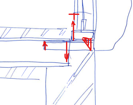
The overhang of the cornice and wind load will produce a moment in the CMU, put the tube into torsion and apply a moment to the angles, which I'm treating as being fixed to the steel beams (please see the attached sketch). Will this moment that is then applied to the beam have the potential to cause uplift in the beam? I am unsure if I can assume that the steel beam is stiff enough to distribute the moment that is applied at its support so that I end up with a lever arm that is the span of the beam (13') by which time the T/C forces are small and will be resisted by the dead load.
I hope this makes sense. Cheers.
I'm dealing with an interesting design problem that I'm trying to resolve. We have an existing building with flat arch terracotta slabs on steel beams at 4'-0" OC. At the top floor, the architect wants to put up a new cornice over the top of the existing brick walls. We'll use reinforced CMU to support the cornice, but don't want to try and tie the rebar into the existing brick. I want to tie the CMU into the beams instead, so I have added a tube underneath the CMU and will connect that to a pair of angles at each steel beam, because the location of the cornice and end of the steel beam don't align (and the architect won't want to move the CMU inside, leaving him with less terrace space).
The overhang of the cornice and wind load will produce a moment in the CMU, put the tube into torsion and apply a moment to the angles, which I'm treating as being fixed to the steel beams (please see the attached sketch). Will this moment that is then applied to the beam have the potential to cause uplift in the beam? I am unsure if I can assume that the steel beam is stiff enough to distribute the moment that is applied at its support so that I end up with a lever arm that is the span of the beam (13') by which time the T/C forces are small and will be resisted by the dead load.
I hope this makes sense. Cheers.