Eng-Tips is the largest engineering community on the Internet

Intelligent Work Forums for Engineering Professionals

Existing Wood Bowstring Truss Evaluation 1

Status
Not open for further replies.

Jason T

Structural
Nov 27, 2018
10
0
0
US
Hello,
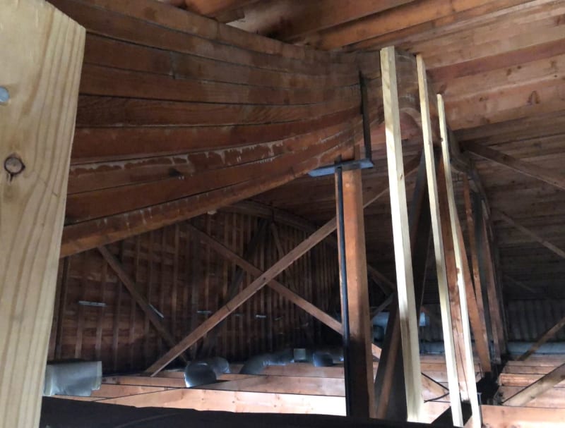
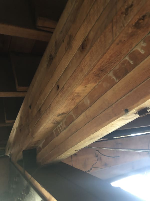
I am currently working on a project with some wood bowstring trusses that span 120 ft and are 16 ft deep at the center. I'm assuming based on conversations with contractors in the area that these were constructed in the late 1950's or 1960's. I do know they were built on site and the top chord consists of a glulam SP member that is (6) 1 5/8" x 9 1/4" with an additional (3) 1 5/8" x 3 1/2" glulam section attached to the bottom of the larger section. The bottom chord is (2) 4 1/2 x 11 members. The panel points are 12 ft o.c. with a vertical 3 1/2" x 3 1/2" member at each location. Evert vertical has a steel plate at the bottom chord and top chord with a steel rod on each side of the chord. The diagonal members are strange, they consist of (2) 2x6's in an "L" shape nailed together.

The building has been vacant for roughly 15 years and a developer is bringing it back to life.

I'm using Risa 3D to model this and the web's are failing with just the standard roof loading. Adding the unbalanced loads makes it look as if this thing should never had been standing in the first place. The interior changes are adding additional supports under some of the trusses and others are getting full height walls built under them for support. This is causing a lot of web members to go into compression and reinforcement needing to be installed.

My question is, would this type of truss be designed as an arch with a tie? I'm treating it like a typical truss analysis. I can't find any sources of information regarding a truss design like this.

Any input, assistance or advice is greatly appreciated.
 
 https://files.engineering.com/getfile.aspx?folder=517e0a00-5a27-4eec-8f44-10e6e573308d&file=IMG_2209.jpg
Replies continue below

Recommended for you

Jason T said:
I can't find any sources of information regarding a truss design like this.

Here's a bit of helpful information: An Update on Bowstring Truss Issues

Jason T said:
My question is, would this type of truss be designed as an arch with a tie? I'm treating it like a typical truss analysis.

It would be designed as both a tied arch and a truss, acting in superposition. That's the genius of the structural form. I would expect your RISA model to already be accounting for this however.
 
Thank you for the information KootK. Looks like I'm going to have my work cut out for me with these.

There is some top chord delamination happening in about 1/4 of the top chord (picture attached). My thoughts for this section were to sandwich the chord on both sides and add horizontal through bolts along with additional vertical through bolts to tie it all back together. Any chance you've had a similar issue in the past?

Thank you again.
 
 https://files.engineering.com/getfile.aspx?folder=6841a585-5a8a-4ec4-b506-f9bbb5bc2a27&file=IMG_2211.JPG
You can look into epoxy injection or penetrating epoxies for means of re-establishing strength if an issue.

Rather than think climate change and the corona virus as science, think of it as the wrath of God. Feel any better?

-Dik
 
Yup... but, it can be a learning experience, too. You, too, can become an expert.

Rather than think climate change and the corona virus as science, think of it as the wrath of God. Feel any better?

-Dik
 
From what I recall there were originally bowstring truss catalogs distributed by manufacturers where you would choose a truss based on some parameters like the required span. It sounded like every manufacturer had their own way of doing things but were pretty consistent about it. I believe back then the most common method of running an analysis was something I've seen referred to as the "graphical" or "Maxwell" method or which I believe was just a quick way of truss design (no arching action). You might be able to find some additional information on this type of analysis in an old truss brochure or the timber construction manual, but, as you've probably guessed, this method was riddled with problems.

As for what method is correct nowadays, I believe the most accurate would be a model that considers the truss "as is". By which I mean you would run the model with assumptions that are consistent with what you saw in the field that would consider the interaction of truss and tied-arch systems working together. This would probably be most representative of what is actually happening to the truss and would give you at least an idea what you're dealing with.

I imagine you could isolate the tied-arch action by changing the web member member properties so that the web members are basically just hangers for the bottom chord. I would say that if the deformations in this "tied arch" model are similar to the deformations in your original "as is" model, you would have an argument to design using "tied arch". However, if you do go with a tied-arch model, its up to you to prove that the tied arch action can be achieved without failure of the truss.

Either way, I would run any potential repair details by whatever contractor will be doing the work. They'll tell you some obvious things like avoid welding, but also other not so obvious things like how they would replace full chords.

 
Jason T said:
Any chance you've had a similar issue in the past?

1) Nothing really on the scale of the problem that you seem to be dealing with.

2) For shallower things, GRK wood screws installed at an angle.

3) For local shear reinforcement, I've seen others do diagonally oriented rebar epoxied into drilled holes.

I hate to say it but, based on what you've shown us so far, I suspect that you might be in for a wild ride with these "trusses":

4) That's some ugly, and serious delamination which gives me little confidence in the on-site fabrication processes.

5) If these things are actually meant to be trusses of some sort, then the joints look awful to my eye. Other than where compression webs would transfer their loads in direct compression, I don't see a single connection with any serious capacity.

Many contractors truly can do some great work without the aid of a structural engineer. My sense of this situation, however, is that the lack of an engineer's involvement has created a system that will have numerous "deal breaker" detailing fails when examined carefully. My advice to you would be to do you best to get a wholistic view of everything that might be wrong with these trusses before you expend too much energy trying to develop solutions to any particular issue. The right answer here may well prove to be a "reinforcement" scheme so invasive that it's essentially constructing new trusses using the existing ones for little more than erection scaffolding.

I'm not trying to sink your project by being a pessimist but, at the same time, I hate to see somebody beat their head against a wall for lack of honest advice.
 
@Jason_T: what's your read on the waviness of the the top chord in the photo below? Is that the intended roof shape of these things or is the intended shape more like one would expect with the gable end in the background? If it's the latter, that's pretty scary as it presents like arch bucking which might be either the result of -- or the cause of -- the delamination problem.

C01_hdxfgz.jpg
 
Thanks for you input Trustthemodel! appreciate your insight.

Kootk, I certainly appreciate the honesty! No need to sugar coat anything here. The only saving grace in my opinion is we are going to be providing column supports under each truss at about 1/3rd points and/or building a continuous wall under some of them for the new design of the space. I've already mentioned to the contractor this will most likely have so much reinforcement you're basically building new trusses which he didn't seem surprised by.

Regarding the photo, that is actually the top chord delaminating in those first 3 panels.

 
are you sure that's glulam?... really looks delaminated.

Rather than think climate change and the corona virus as science, think of it as the wrath of God. Feel any better?

-Dik
 
OP said:
Regarding the photo, that is actually the top chord delaminating in those first 3 panels.

Delaminating and then assuming that wavy shape, right? As in it wasn't wavy shaped to begin with?

OP said:
The only saving grace in my opinion is we are going to be providing column supports under each truss at about 1/3rd points and/or building a continuous wall under some of them for the new design of the space.

You've got a reasonably stout bottom chord. With 1/3 point support, you might just call that the structural system on it's own and then just post up to the top chord at tightly spaced intervals as required. If it would work, it could save a lot of reinforcement effort and a lot of design effort. The down side of that would be the potential for some new foundations I suppose.
 
Dik, the other sections of the chord look like they're in good shape. The building hasn't been climate controlled for I think 15 - 20 years and some have suggested that aided in the delamination. Here's a shot of the section at bearing.

IMG_2212_ulmdqa.jpg


Kootk, correct.... the chord was not wavy to begin with. And yes, decent size footings under those posts! The developer wants to try and keep that truss look if possible. So far I'm looking at utilizing steel angles to brace the diagonal and vertical webs, 1/2" to 5/8" plate on each side of the top chord with through bolts (2 per row) spaced as required to reinforce that delaminated section. I'm also looking at adding additional vertical bolts through the top chord section to tie those delaminated members together better.

It's hard to see in that photo, but they do have vertical through bolts through the top chord every 3 - 4 ft o.c. I think that is the only reason that chord didn't completely separate when it delaminated like that.
 
OP said:
So far I'm looking at utilizing steel angles to brace the diagonal and vertical webs

Just make sure the connections at the ends of the truss webs check out as that is likely your weak point.

OP said:
1/2" to 5/8" plate on each side of the top chord with through bolts (2 per row) spaced as required to reinforce that delaminated section.

I don't see bolts of that diameter as a feasible way to restore horizontal shear capacity when every lamination has delaminated. Rather, one or more of these things will occur:

1) The bolts will land at the lamination joints and be useless or:

2) The bolts will land mid-lamination and take out 1/3 to 1/2 of the lamination's sectional capacity.

3) Without epoxy etc, there will be too much slop in the bolt holes for the bolting to really pick up load.

Besides, to make this work, you'd have to bolt all of the laminations. Swiss cheese.

OP said:
I'm also looking at adding additional vertical bolts through the top chord section to tie those delaminated members together better.

Again, without epoxy etc to stiffen that load path, connection slop will likely render this strategy ineffective.

 
Kootk, any suggestions with how to approach this? I saw a webinar where they discussed using steel plates on the top and bottom with vertical bolts on the outside of the chord to clamp the delaminates sections. The purlins would be a pain to work around though.

I’m not sure if the contractor would want to attempt adding epoxy to try and glue the sections together again. It might have to come to that though.

My biggest concern is the web connections to the chords. That’s going to be some fancy steel fabrication in my mind.
 
Jason_T said:
Kootk, any suggestions with how to approach this?

KootK said:
You've got a reasonably stout bottom chord. With 1/3 point support, you might just call that the structural system on it's own and then just post up to the top chord at tightly spaced intervals as required. If it would work, it could save a lot of reinforcement effort and a lot of design effort. The down side of that would be the potential for some new foundations I suppose.

You not diggin' that? Like dik, I'm getting pretty trepidatious about even calling the top chord "glulam" in any meaningful sense. Suck-lam. We do have to remain solution focused in order to stay in business but there are limits.

Jason_T said:
I saw a webinar where they discussed using steel plates on the top and bottom with vertical bolts on the outside of the chord to clamp the delaminates sections.

Was the goal to restore interlaminate shear capacity with friction? If so, I'd have some concerns about cross grain creep neutering the tension in the bolts over time. Granted, anything presented in a webinar does posses some measure of credibility. You know, compared to random nutballs on the interweb.
 
Thanks Kootk, I wasn’t negating adding additional verticals to brace that chord, just seeing how feasible, if at all, you thought my proposed solution would be.

Of course the presenter of the webinar didn’t get into great detail regarding the methods suggested. Kind of just mentioned options and moved on.

I think the best solution would be to replace the roof! Doubt that’s in the budget though.
 
Jason_T said:
Thanks Kootk, I wasn’t negating adding additional verticals to brace that chord...

To clarify, my proposal was not to add verticals to merely brace the chord but, rather, to essentially abandon it with respect to any primary structural role. There is a subtle difference there. Any scheme that attempts to restore the system's true arch/truss function would need to start with jacking the top chord back to it's original position. And that won't be cheap either.

Jason_T said:
Of course the presenter of the webinar didn’t get into great detail regarding the methods suggested.

Yeah, all kinds of things tend to sound clever until you get down to the brass tacks of making the details go. Up until Christmas I thought it was "Brass Tax" so I'm doing my best to use that phrase properly for a few months until it sticks...
 
The contractor is already planning to try and slowly bring that arch back to those chords and much as possible. They’re in the process of shoring them up in the meantime since it’s winter here in Michigan and the snow is coming down.

Any reinforcement scheme I was looking at would be done if and when the contractor can restore the shape. I wasn’t intending to reinforce as is, I should have clarified that better.

Thanks again for all the good advice.
 
Status
Not open for further replies.
Back
Top