Eng-Tips is the largest engineering community on the Internet

Intelligent Work Forums for Engineering Professionals

Expansion Loop Design - Anchor point placement 2

Status
Not open for further replies.

nikolastrojman

Industrial
Jul 17, 2007
59
0
0
AT
Hi!

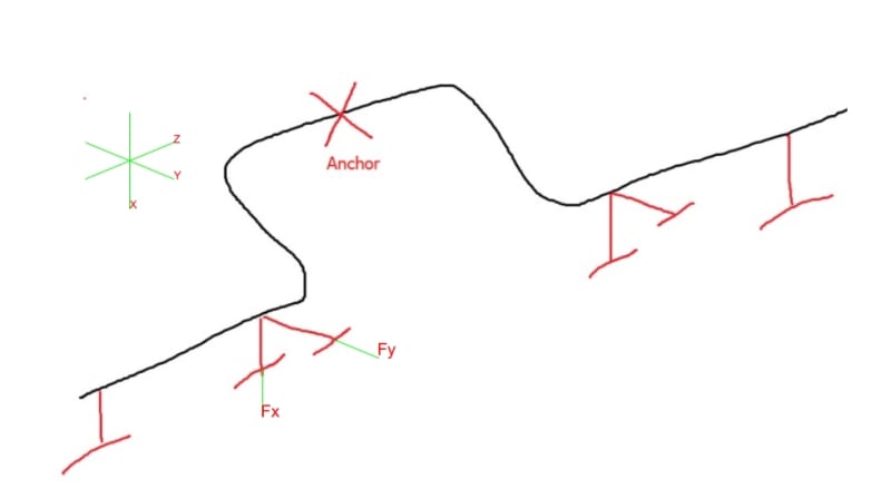
I have a question regarding the expansion loop design and placement of anchor points. Does it make any sense to place an anchor in the middle of the expansion loop?
2024-07-01_11-19_brn86b.png


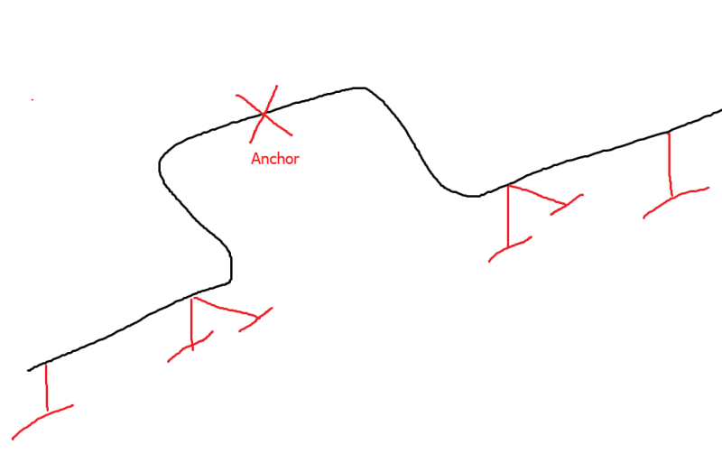
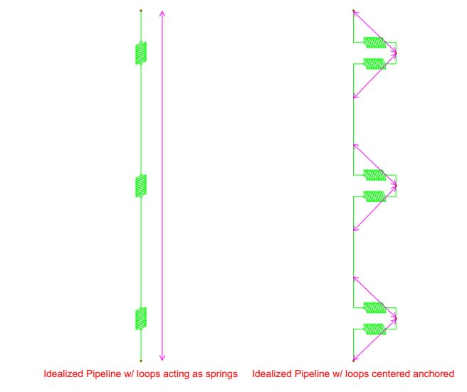
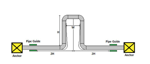
The conventional way (and the proper way) is to put anchor on both sides of the loop in order to use it´s inherent flexibility to reduce thermal expansion stresses and support displacements.
One of our subcontractors suggested to put it in the middle of the loop.

BR
Nik
 
Replies continue below

Recommended for you

Where's your anchor at the moment?

Typicaly you try and get the expansion loop in the middle between tow anchors or line stops to get the loop to be equal.

But if the "neutral" point where your X is moves a bit, so what?

It does turn the loop inot essentially two angle expansion legs, but you introduce a third bending location around the anchor unless you all the loop to move horizontally and not anchor it.

I've seen line stops in an axial direction before, but could never see the reason for it.

Remember - More details = better answers
Also: If you get a response it's polite to respond to it.
 
ACTUALLY BOTH ARE WRONG!

If you put an anchor at both sides of a loop, you do nothing.
Pipe to the right moves right.
Pipe to the left moves left.
Pipe in the LOOP bends.
No expansion movement of those long pipes is taken up by the loop's flexibility.
You wasted ALL your money.

If you put one anchor in the middle of the loop,
You wasted half your money.
All pipe to the left moves left, but only half the loops flexibility reduces axial stress.
All pipe to the right moves to the right, but only half the loops flexibility reduces axial stress.
MSE on both ends catches that axial stress.

"Proper", or typical placement is
Movement sensitive equipment (MSE)
Anchor (A)

MSE - A------pipe-----------LOOP------------pipe----------A- MSE

all pipe movement is directed TOWARDS THE LOOP!
All high stresses are contained in the pipe, none goes to MSE.


--Einstein gave the same test to students every year. When asked why he would do something like that, "Because the answers had changed."
 
As others have said it depends on the rest of the system and connections. An anchor in the middle of the loop CAN work, but it's not the norm and may not work in some situations.

The typical arrangement is an anchor in the middle of the piping between loops, similar to this picture where you have additional loops based on the pipe run.
Figure-1-expansion-devices_rknu0c.jpg
 
NTS Not to scale

Normally guides would not be placed so close to anchors, as the object is to restrict kick out caused by loop bending. Distance from guide to anchors would probably be at least 2H, probably a lot more.

Placing the guide at 2H is an attempt to locate them at bending inflection points of the piping near the loop, where lateral movement from loop bending is near zero, thereby also obtaining minimum loads going to the guide. Guides are often not present at all if loop kick out is insignificant without guides.

--Einstein gave the same test to students every year. When asked why he would do something like that, "Because the answers had changed."
 
OP,
I am not trying to be overly critical, but it gives me pause that you are at the stage were a sub is providing constructability input and it seems pipe design hasn't even been completed. There's a large amount of consideration and variables in doing pipe design and calculating pipe stress and anchors and IMHO should never be done or wait to be done as part of field installation. As 1503-44 noted, are you protecting MSE? If so, then that should be dictating your anchor points and pipe supports.
 
In long pipe runs with multiple loops you do sometimes find line stops midway between loops to prevent one loop doing less than another loop and hence one getting more expansion than it was designed for.

Is that what the subcontractor meant?

So it goes MSE-A-P-loop-P-A-P-Loop-P-A-P.....

Remember - More details = better answers
Also: If you get a response it's polite to respond to it.
 
A center loop is for keeping axial compression stress below the critical buckling length, or below the combined stresses allowable, in the pipe itself, whichever is less. Guides can shorten the effective buckling length, but don't do anything to reduce axial stress. Center loops are common on long high temp steam lines. Often one every 100ft.

--Einstein gave the same test to students every year. When asked why he would do something like that, "Because the answers had changed."
 
I would ask the subcontractor why he thinks this and if he has any stress analysis experience. Typically you don't see anchors on expansion loops. However I am sure there could be a reason to put one there, in most piping configurations you would avoid putting an anchor on an expansion loop.

As others said the anchor should be placed to avoid loads on equipment and to allow the pipe to expand freely into the expansion loop while the anchor takes the thrust load due to 1) friction of thermally expanding pipe against supports 2) force of bending of expansion loop. Say you have two or three loops as shown in a row on a long length of pipe, with an anchor on the loop where shown, the friction load at pipe supports on a long length of piping between loops may not be consistent and may cause more themal expansion into one loop than another. Placing the anchor between loops on the piping forces even themal expansion into all loops and all frictional support forces due to thermal expansion are transfered evenly to the anchors and not to the loop. A anchor between loops also insures mostly axial loads on the anchor and reduces torsion loading which structurally is harder to design for.

Also the anchor should be placed such that on thermal expansion cycles the piping will go back to its original cold position. If placed on a real flexible loop the thermal expanded pipe, with uneven friction forces at supports, may want to start displacing unevenly axially but may not return to the same place during heating/cooling cycles and begin to walk across supports a few inches or more.

Also consider that placing an anchor on the loop I believe will significantly reduce the flexibilty of the loop as it limits rotation of the loop and rotation of elbows is a major contributor in taking up thermal expansion movement. So you will need a much larger loop for the same thermal expansion.

 
A "dog leg" on both sides. [puppy]
It's better than no flexibility at all.

--Einstein gave the same test to students every year. When asked why he would do something like that, "Because the answers had changed."
 
Actually it has nothing to do with protecting sensitive equipment (MSE).

We have rather high piping loads being transferred to the support structure (8m high frame) foundation e.g. 130-200kN depending on the axial stop location on this long pipe run.
We are talking about 42" flare line located in an area where earthquake activity is significant, and the earthquake imparts a big portion of the total load on the axial stops.

The idea of the subcontractor is to dislocate the anchor bay structure to the middle of the expansion loop as shown on the picture before, where they would build a proper structure which will be able to withstand such high loads.

Axial stops are currently located at the position where stress analysis shows axial (longitudinal) displacements smallest i.e. 0 mm or 2-3 mm.
 
Well its difficult to comment further only being give a small snapshot of the whole system and what the issue is until now.

Why have a line stop when there isn't any movement? No movement, not much force surely?
And why not place the line stop on the main run where there is little movement?
If you key issue is earthqauke, I can't see why location would make any difference to that, but in the middle of the loop can cause the loop to become unbalanced.

And is a line stop only in one direction / plane?

you asked does it make sense. I think the answer from most people here is no.

Remember - More details = better answers
Also: If you get a response it's polite to respond to it.
 
OP,
You have given some important insight to the problem in your second response.
The problem is: high piping load transferred to the existing support structure. Your plant is in an earthquake zone and the major loads on the flare header/support comes form the seismic load.
The contractor has definitely suggested an unconventional loop design which most of the forum members have argued.
Here are some options:
1. Expansion loops are provided to take expansion/compression of the piping system. It has nothing to do with seismic load.
2. Seismic load is dependent on weight of the piping and its content. Other factors are location (seismic zone) and height above ground.
3. I am not sure how long the flare header is, what you said is it's a long pipe run. If it;s so is it possible to add another offset/loop to relieve the load from one anchor support?
4. What is the stress analysis report after placing the anchor in the middle of the loop (contractor proposed)? Does it pass the code requirement?
5. I am sure that the expansion loop is designed 2D and sloped towards the KOD at 1:500


GDD
Canada
 
OP,
Thank you for the additional information. I agree with GD2 approaches. A few more thoughts for consideration. I've always seen and designed anchor points in line with the pipe. Why, because that's how I was taught to design them, and it makes sense intuitively when you think about the forces. To your sub-contractor's defense, you may have a Rain Man of a sub, but I think you'll find when you do the pipe stress, there will be unintended consequences. I would think that anchoring your loop in the middle would halve the effectiveness, requiring a larger loop and more structure. As GD2 noted, why not put in another loop? I would also be concerned that anchoring offset to the piping would induce some torsional stress concentrations. All you can do is run the numbers.
 
Is this a field change during construction proposed by the construction contractor? If so then I would not do anything until discussed with the original engineering firm and have them confirm by redoing all calculations. The contractor also will probably want a large extra for doing this change so I would try to avoid any major field changes such as this.

With the anchor on the expansion loop the large seismic loading will still exist but just be transfered to the anchor through the loop legs causing a lot of deflection and bending of the legs and possible overstressing. Also the flexibility of the legs when transferring the seismic load may cause resonance of the piping vibration natural frequency mode further causing issues with overstressing and large pipe movements. This needs to be totally reanalyzed by the original piping engineer.
 
I like Snichsters great advice. Contractor better have a viable reason. To deviate from the original design. I would as two Xtra opinions on this matter. If there is a flaw
And if the contractor is correct because they build the pipe system . Because they have good
Procedure practices. The I would suggest to have a consultant analize it, with heavy background and experience. To certify it.
 
OP,
Based on the information in the first post I had assumed you were much further along in the project than I now think you are. It appears preliminary pipe stress has been completed and due to the high seismic conditions and pipe loads, substantial structure was going to be required to resist those loads. cue the subcontractor "Hey, how about we do this?" Now comes the question; is it worth pursuing the subcontractor's idea and redoing the basic engineering that's already been completed?
I may be totally off base here and if so, feel free to ignore all of the following or anything else. Since I don't have pipe design software on my personal computer, the best I could do to make sense of it is FBD it. The following are only questions I have based on the FBD.

In the sketch you provided Fx is resisted by normal forces, being your structure and foundations. How is Fy being resisted?
Screenshot_4-7-2024_10545__kccps4.jpg


The FBD on the left shows the forces being transferred in line with the guides, using springs as idealized loops.
The FBD on the right shows a now added axial force acting on the guides based off of center loop anchoring. Will this prevent the guides from freely moving? What additional stress concentrations now exist? Even restraining the Fy in the sketch, will additional reaction forces occur axially to the rest of guides?
Screenshot_4-7-2024_111653__tp1ofc.jpg
 
Status
Not open for further replies.
Back
Top