Eng-Tips is the largest engineering community on the Internet

Intelligent Work Forums for Engineering Professionals

  • Congratulations waross on being selected by the Tek-Tips community for having the most helpful posts in the forums last week. Way to Go!

Expertise/experience on expansion joint control rods

Status
Not open for further replies.

nondimensional

Mechanical
Jan 24, 2019
32
0
0
US
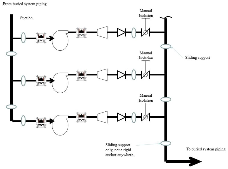
Does anyone have any experience in designing/sizing the control rods for the expansion joints indicated in the picture below? I have zero thrust blocks/anchors in the piping system except where the pipe emerges from the ground on the suction header and goes back below ground on discharge header (the buried portion is considered anchored). All the supports I have are sliding supports. The expansion joints are required to be able to pull the pump out of service and reinstall. Assume a slight (~1/8 inch) misalignment that needs to be compensated by the joint. NO EXPANSION is preferred whatsoever - to avoid any loads on pump nozzles. Pumps are installed on solid concrete foundation, anchored down to the foundation.

4000 gpm each pump
16-inch pump suction (15.25 ID)
14-inch pump disch (13.25 ID)
24-inch suction header
30-inch discharge header
Ps = 20 psig
Pd = 120 psig
Pdiff = 100 psig

Capture_wku2ue.jpg
 
Replies continue below

Recommended for you

IMO, the rods on the expansion joint are to control and allow only for a one-dimensional movement with a specific displacement. Providing the force and movement, the Manufacturer of the Expansion Joint may provide you the required details.
 
From my recollection of the miseries a piping engineer colleague faced on a similar problem on an EPC project, there appears to be some missing information:
a) Ambient temp range, lower design temperature, upper design temperature.
b) Sparing philosophy : would this be a 3x50% running configuration ?
c) Exposed above ground piping and pump insulated or bare?
 
There should also be an "Isolation" Valve on the suction side of each pump.
Without them you will need to shut-down and drain the whole system to replace or repair one pump.

Sometimes its possible to do all the right things and still get bad results
 
@mk3233:
Allowing any movement in excess of 10 mils (0.010 in) would be in violation of the Hydraulic Institute design standards. My question is does that apply here given the setup of piping.

@georgeverghese:
a) assume 80F ambient at installation, with 60 to 85 degF for water temperature inside the pipe.
b) 3x 4000 gpm. No spare.
c) Exposed above grade piping in the pump station is coated.

I am unable to see how insulation matters at all. This is not about galvanic corrosion.

@pennpiper:
Agree, isolation valve is required. I am more interested in the expansion joint detail.
 
@nondimensional,
The insulation would have made a difference to the expansion bellows duty if design temperatures are high. Since operating temps here are close to ambient, it wouldnt.
 
Allowing any movement in excess of 10 mils (0.010 in) would be in violation of the Hydraulic Institute design standards.

@nondimensional,
What is the movement allowance applied to as stated in the Standard? Is it for the pump nozzle, drive shaft, etc., or for the expansion joint?
 
Per code, maximum allowable stretch of the rods is 10 mils.

Note that the control rods should be completely tied down during assembly before starting the pump for the first time. There should only be the very small allowable movement (10 mils) due to internal pressure.

My main question: there are people here who work on some very high pressure pumps which thus result in a very high axial force on the pump discharge pipe. What are the best practice for designing a joint where a thrust block is not installed between the pump and the joint.

Thanks for the input.
 
IMO, since the pump won't be changed, the piping should be designed to accommodate the expansion joint if no one can make it to meet the required movement.
 
Status
Not open for further replies.
Back
Top