Continue to Site

Eng-Tips is the largest engineering community on the Internet

Intelligent Work Forums for Engineering Professionals

  • Congratulations GregLocock on being selected by the Eng-Tips community for having the most helpful posts in the forums last week. Way to Go!

Explain purpose of this diode

Status
Not open for further replies.

AlveyStreet

Electrical
Jan 6, 2011
3
Refer to astron linier PSU schematic:-
I aquired this broken 723 based PSU with blown components:-
CR1+2 35Amp diodes, 723 reg, q2, 3771 driver and diode CR5. I can easily repair, but cannot understand purpose of CR5. It apears to make circuit self destructive. If crowbar trips, output collapses. This causes 723 to drive high current thru be junction of Q2, CR5 and 2n3771. Current is NOT limited, as CR5 does not allow R1 (which is in parrallel) to do its job of limiting 3771 base current to 1 Amp(approx).
Can anyone explain purpose of CR5, or for that matter why R1 is made S.O.T by addition of R1X.
Thanks
 
Replies continue below

Recommended for you

Hmmm... Maybe:

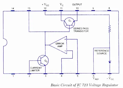
What comes out of the 723 on pin 10 originates from what goes into pin 11.

IC-723-Voltage-Regulator-Basic-Circuit.jpg


And for your circuit, that's got R14 (330 ohms) limiting the current into pin 11.
 
I suspect the R1 and CR5 are intended to provide temperature compensation (but I'm not sure). Is CR5 mounted so that it's in thermal contact with a power transistor or a heat sink? If it is, then that would more-or-less prove it.

Standby for others' input.


That's a nice power supply. Well worth fixing, especially since the parts are all garden variety and cheap.
 
Thanks VE1BLL, I agree that Iout of pin 10 is limited, but it will still be enough to saturate Q2 and, I believe cause the problems. When FEC deliver spares, I can run some tests. At least you have a theory about CR5, which is more than I have. i will repost after some tests.
Thanks Alvey
 
you'll see CR5 used on similar devices to help prevent instability through the high gain stage. If your circuit runs satisfactory without it, omit it.
 
Thanks automatic2. The diode is placed on a PCB with other components, and does not appear to be used for temp.comp. I haven't heard of this form of stability control. It would appear to increase drive level on current-increase heavy transients. I had decided to remove the component initially, while testing the crowbar action. If it works OK, then I doubt if it will be refitted. Many thanks gentlemen.
Regards alvey
 
It looks to me like the designers were having trouble getting enough base drive current into Q101, Q102 during peak load current transients, so they put in CR5 to boost the base drive a bit. This may have led to the failure you have seen. Removing CR5 will probably work fine. The output peak currents may be somewhat less, but the unit should be more reliable.
 
Maybe they are linearizing the gain of the 3-transistor Darlington vs. load current by putting a diode/resistor network in there which increases the gain at higher currents where beta is falling off. With more current through the parallel CR5||R1||R1X combination you get less voltage across it due to CR5 so the open loop transconductance (Iout vs. V(pin10)) goes up to maintain regulation. But, maybe not... Power supplies are great fun to reverse engineer!
 
Status
Not open for further replies.

Part and Inventory Search

Sponsor