PeteCod
Mechanical
- Jan 5, 2015
- 11
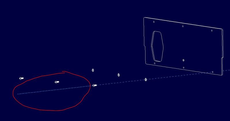
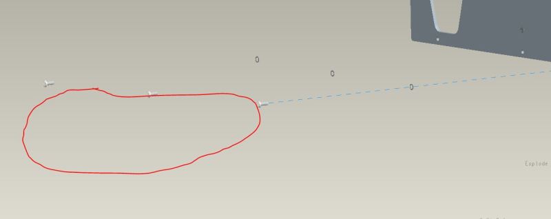
Hello all! To start, I am using Pro Engineer Wildfire 3.0. In the passed 2 or so months, I have been experiencing problems of escalating degrees relating to explosions. I have been creating explosion lines the same way for about 2 years now, and just recently have I started having problems. It all started with one of my explosion lines in a set of screws, that were all exploded together. In the model all of the explosion lines looked good. When I switched over to the drawing, all but one of the explosion lines went from the screw to the mating threads. The remaining line stopped short, with no apparent reason. Up to that point, I had never seen an explosion line in a drawing not match the one shown in the model. I tried clicking different cylindrical surfaces on the feature, and the axis, without any success. Since that first time, I have been experiencing the same problem more and more. Now I am lucky if any of my explosion lines work the first time. I have found that to get them to look right in the drawing, I must create them in the model, look at the drawing, look back at the exploded model (at which point the lines will not be where the were when I created them, but they will still not match the drawing), then I must drag a random point on the explosion line a seemingly arbitrary distance, check the drawing, and if I am lucky, it will look right. Otherwise I must drag a random point again.
In addition to the line problems, I have noticed that after I explode an assembly, if I view the drawing, and then go back to the assembly, the assembly is exploded incorrectly (and seemingly randomly) until I double click the explosion again in the view manager.
I have a suspicion that there is something going wrong in the program, or in the file system somewhere, but I have no idea where to start looking or how to fix it. If someone could provide any help at all, I would be very happy. If there is anything that you would like clarified, or some screenshots of what I am talking about, please let me know. Thanks!!!
Edit: I have attached some pictures showing how the drawing and the model differ. Notice in the drawing how the explosion line shoots out of the top of the screw, but in the model, it does not.


