Hello all,
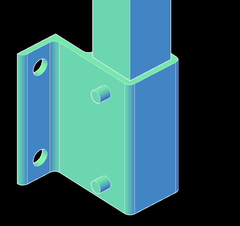
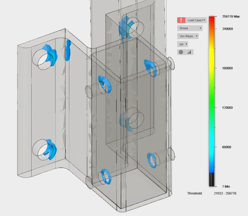
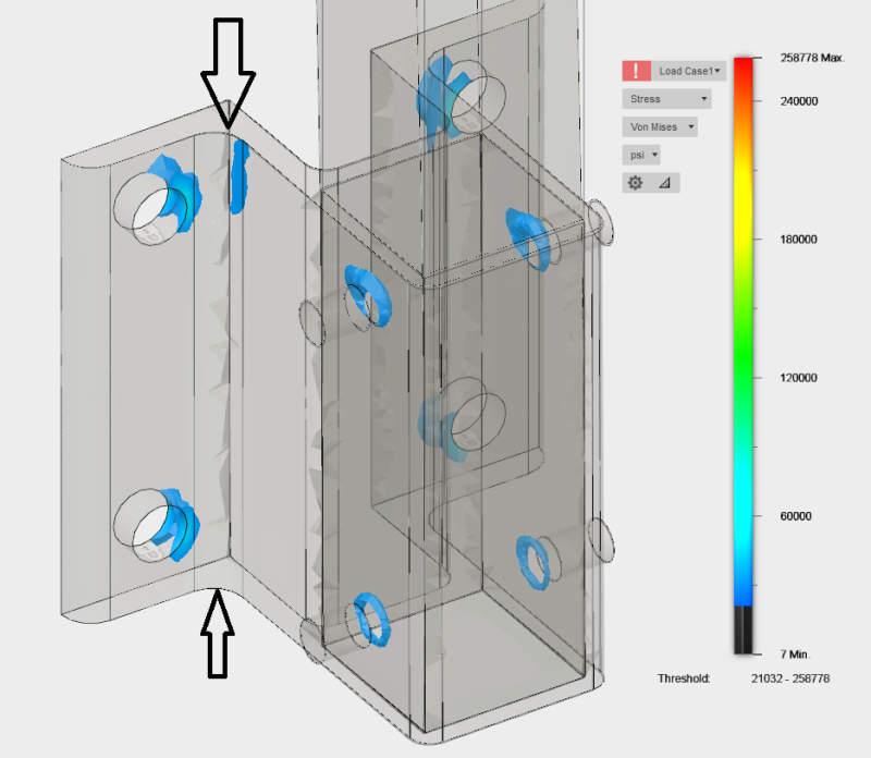
I'm tasked to design the section of an extruded 6061-T6 aluminum side mounting bracket which will accept a 2" square aluminum tube or bar post of a guard railing. The post will be thru-bolted to the bracket using up to two 3/4" diameter stainless steel threaded rods. I do New York City Building Code guardrail calculations almost daily and know what load/moment it will need to withstand but want to ensure all the wall thicknesses & dimensions of the extrusion are adequate to withstand the design load. I've attached something I found on CR Laurence's website for a very similar bracket. To me the attached document looks like it focuses mostly on the anchors and is not very thorough in regards to the bracket itself. A few months back I found Autodesk Fusion 360 which does FEM analysis and will show stresses. The issue I ran into with the model is no matter what there will always be some mesh tetrahedrons that are over an allowable stress of about 21,000 psi. I'm not sure if I can use the FEM model in a report since it will always have some finite elements that are over stressed. I'm using ASD design method and the maximum moment the bracket is to be designed for is 37,895 in*lb & 1,763 lb of shear. (Loads perpendicular to plane of wall/surface)
Can anyone advise on the proper calculations to run in order to adequately size the section?
Thanks!


