-
1
- #1
Navigation
Install the app
How to install the app on iOS
Follow along with the video below to see how to install our site as a web app on your home screen.
Note: This feature may not be available in some browsers.
More options
Style variation
-
Congratulations cowski on being selected by the Eng-Tips community for having the most helpful posts in the forums last week. Way to Go!
You are using an out of date browser. It may not display this or other websites correctly.
You should upgrade or use an alternative browser.
You should upgrade or use an alternative browser.
Failure about to happen? 14
- Thread starter JAE
- Start date
- Status
- Not open for further replies.
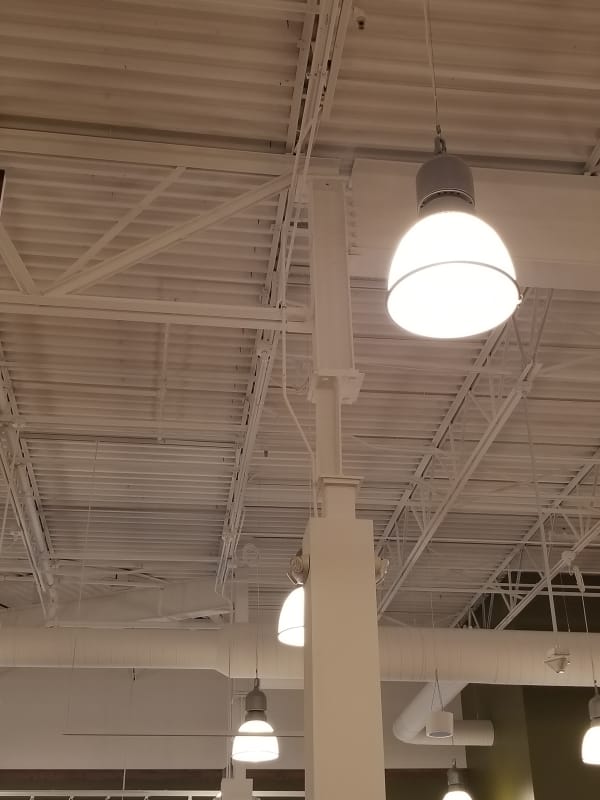
"that column looks a little undernourished to me"
That seems like an awfully judgmental opinion; we have no idea whether it has a metabolic disorder or something else.
TTFN (ta ta for now)
I can do absolutely anything. I'm an expert! faq731-376 forum1529 Entire Forum list
That seems like an awfully judgmental opinion; we have no idea whether it has a metabolic disorder or something else.
TTFN (ta ta for now)
I can do absolutely anything. I'm an expert! faq731-376 forum1529 Entire Forum list
The other column in the picture looks different; whether that makes it better is another matter.
TTFN (ta ta for now)
I can do absolutely anything. I'm an expert! faq731-376 forum1529 Entire Forum list
TTFN (ta ta for now)
I can do absolutely anything. I'm an expert! faq731-376 forum1529 Entire Forum list
GregLocock
Automotive
I was gently wondering if the bit of roof on the right was an extension, and they were expecting a LOT of lateral motion in the main roof due to say sun load. The plate would act as a leaf spring and tolerate that lateral motion. I've (well, a cluey CAD guy working for me) done something like that in the past on a smaller scale.
Cheers
Greg Locock
New here? Try reading these, they might help FAQ731-376
Cheers
Greg Locock
New here? Try reading these, they might help FAQ731-376
LittleInch
Petroleum
That UC on the left looks a whole heap heavier than the truss on the right and is supported on what looks like a pretty flimsy piece of angle iron... That must be putting a pretty serious moment on the strut top and hence a decent lateral force on that piece of sheet steel.
It is a bit on a wonder as to why it hasn't actually bent and collapsed yet.
Remember - More details = better answers
Also: If you get a response it's polite to respond to it.
It is a bit on a wonder as to why it hasn't actually bent and collapsed yet.
Remember - More details = better answers
Also: If you get a response it's polite to respond to it.
12345abc6ttyui67
Structural
Why the predrilled holes in the stub beam? Presumably for something to be attached. I'm more concerned about what's missing.
Guest
Around 2001, one person was killed in a mall roof collapse in Sarnia ON. It was due to snow load, although total average accumulation on the roof was well within allowable. A combination of drifting and a significant step (basically an 8 foot transition in elevation) led to a very heavy drift pileup at one location. Thankfully (relatively) it happened before the mall opened, so there were no shoppers inside yet.
I can't be sure but I think that roof was better supported than this one appears to be. Actually the first thing in the photo that caught my attention was how flimsy the roof panels are, especially to the left of the slender column.
"Everyone is entitled to their own opinions, but they are not entitled to their own facts."
Guest
cooperDBM said:It looks so wrong but also so deliberate. Is the column below just clad or is it concrete, perhaps acting as a cantilever? Is it tapered or is that just the perspective?
All of the above?
"Everyone is entitled to their own opinions, but they are not entitled to their own facts."
- Thread starter
- #32
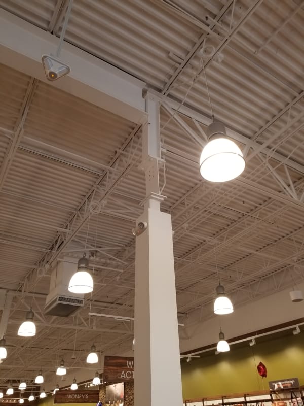
OK - so he went back last night and took another photo of it from the other side.
There is a single stiffener on that opposite side which makes me feel a little better.
The load coming down from above is still eccentric to the "T" shaped piece of column (beam web plus stiffener) but at least there's something.
However, if the WF roof beam is fully loaded the eccentricity of the load might be too much.

Check out Eng-Tips Forum's Policies here:
faq731-376
There is a single stiffener on that opposite side which makes me feel a little better.
The load coming down from above is still eccentric to the "T" shaped piece of column (beam web plus stiffener) but at least there's something.
However, if the WF roof beam is fully loaded the eccentricity of the load might be too much.

Check out Eng-Tips Forum's Policies here:
faq731-376
12345abc6ttyui67
Structural
Any thoughts on the purpose of the 6 predrilled holes in the short beam section (shown in the original photo). For attachment of bracing?
Oh, that SO MUCH BETTER...
It looks like the column in the back has some similarity, but it's hidden behind the light fixture.
TTFN (ta ta for now)
I can do absolutely anything. I'm an expert! faq731-376 forum1529 Entire Forum list
It looks like the column in the back has some similarity, but it's hidden behind the light fixture.
TTFN (ta ta for now)
I can do absolutely anything. I'm an expert! faq731-376 forum1529 Entire Forum list
JohnRBaker
Mechanical
It looks like someone decided to raise the height of the roof by a couple of feet AFTER all of the steel had been cut. That fabricated angle-iron segment looks like a filler piece to me.
John R. Baker, P.E. (ret)
EX-Product 'Evangelist'
Irvine, CA
Siemens PLM:
UG/NX Museum:
The secret of life is not finding someone to live with
It's finding someone you can't live without
John R. Baker, P.E. (ret)
EX-Product 'Evangelist'
Irvine, CA
Siemens PLM:
UG/NX Museum:
The secret of life is not finding someone to live with
It's finding someone you can't live without
structSU10
Structural
So I was curious and checked this like a stepped column. assuming 20' tall, and top 5' is equal to a WT4x15.5, bottom is an HSS8x8x3/8, the critical buckling load would be about 94 kips, or an allowable load of about 56 kips, neglecting eccentricity. that is a 30'x30' bay at 60 psf allowable.
GregLocock
Automotive
So much for the leaf spring theory!
Cheers
Greg Locock
New here? Try reading these, they might help FAQ731-376
Cheers
Greg Locock
New here? Try reading these, they might help FAQ731-376
HamburgerHelper
Electrical
It would be funny if that was an unneeded pillar and instead of tearing the pillar down they connected it to just keep it upright.
------------------------------------------------------------------------------------------
If you can't explain it to a six year old, you don't understand it yourself.
------------------------------------------------------------------------------------------
If you can't explain it to a six year old, you don't understand it yourself.
- Status
- Not open for further replies.
Similar threads
- Replies
- 1
- Views
- 3K
- Replies
- 12
- Views
- 7K
- Replies
- 10
- Views
- 4K
- Locked
- Question
- Replies
- 1
- Views
- 2K
- Locked
- News
- Replies
- 57
- Views
- 2K

