341968
Electrical
- Sep 20, 2003
- 32
Dear All,
Could you please mentioned the actual reason of the following false tripping of two healthy feeders due to a single line to ground fault on the adjacent feeder.
Details are as follows: on
All three feeders are being fed from the same bus 6.6KV. Just adjacent to each other like feeder1,2 and 3. Feeder 3 had SLG fault and it caused feeders 1 and 2 also tripped on the same time.
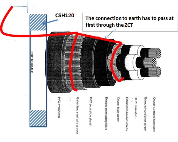
Faulty Feeder 3 : 6.6 KV Total length 35KM (Underground cable 3x50Sq.mm CU/XLPE/STA/PVC), CSH 120 (ZERO SEQUENCE CT) with SEPAM relay 1000+T42.
Over current setting 50/51: (Active Group A) ELEMENT1---STANDARD INVERSE TIME: 10A Delay 1S
ELEMENT2---STANDARD INVERSE TIME: 100A Delay 100mS
Earth fault setting 50N/51N : DEFINITE TIME 7A Delay 100Ms
One of its phase grounded due to excavation at 26km from plant.
Alarm recorded by SEPAM DIRECTIONAL EARTH FAULT
Healthy Feeder 2which also tripped : 6.6 KV Total length 25KM (Underground cable 3x50Sq.mm CU/XLPE/STA/PVC), CSH 120 (ZERO SEQUENCE CT) with SEPAM relay 1000+T42.
Over current setting (Active Group A) ELEMENT1----50/51: STANDARD INVERSE TIME: 10A Delay 1S
ELEMENT2------DEFINITE TIME 100A Delay 100Ms
Earth fault setting 50N/51N : DEFINITE TIME 7A Delay 100Ms
Alarm recorded by SEPAM EARTH FAULT
Healthy Feeder 1 which also tripped : 6.6 KV Total length 20KM (Underground cable 3x50Sq.mm CU/XLPE/STA/PVC), CSH 120 (ZERO SEQUENCE CT) with SEPAM relay 1000+T40.
Over current setting (Active Group A) ELEMENT1----50/51: DEFINITE TIME: 300A Delay 100mS
ELEMENT2------STANDARD INVERSE TIME 30A Delay 1S
Earth fault setting 50N/51N : DEFINITE TIME 7A Delay 100Ms
Alarm recorded by SEPAM EARTH FAULT
Alarm recorded by Incomer feeder for the bus BLOCKING TRANS.
Could you please explain the actual reason and measures to be taken to avoid such false tripping.
Best Regards.

