Continue to Site

Eng-Tips is the largest engineering community on the Internet

Intelligent Work Forums for Engineering Professionals

  • Congratulations IDS on being selected by the Eng-Tips community for having the most helpful posts in the forums last week. Way to Go!

fan speed and Voltage 4

Status
Not open for further replies.

PaulLag

Mechanical
Jul 26, 2013
106
Hi there,
Second doubt.
I have learned that the rotational speed depends by the number of poles and frequency only.
Why then a fan connected in delta and star connection has a different speed, even though it is the same fan and fed at the same frequency ?
I admit it is a basic question.
Could anybody suggest me a link or a book to buy in order to clarify these doubts ?
thanks !
 
Replies continue below

Recommended for you

I have nothing to add.
Read again my two posts from 8 March. No need to repeat.


Pretty much what I expected. "It works" but I can't prove it.
 

Do you expect that I will teach you something more, after your inappropriate reactions?
Certainly, I will not.
The proof is already in initial question.
PaulLag said:
Why then a fan connected in delta and star connection has a different speed, even though it is the same fan and fed at the same frequency ?
I may have a difficulties with English language but I'm sure, PaulLag is not asking " is this possible?" but " why it is possible?".
But, it seems, you can't realize that it is possible?
Your stubborn assertion is: it is about Dahlander winding not D/Y connection. OK. I hope someone will give you a "star" for this.

Quote any of my statements to be inaccurate.
None.


OK, I'm just going to throw together a little data to show why you can not speed control standard induction motors via applied voltage.

Attached is the data from literally the first 75hp motor data that I found. Nothing cherry picked here. I just grabbed the data from the first 460V premium efficiency motor that came up in the list. I put the full-voltage curve data into EXCEL and then calculated what the torque and current would be if the motor was star connected instead of delta. I also plotted the torque curve for a typical fan. This image is the results.

2017-03-10_08_44_58-Book1_-_Excel_fj5t0k.png


So, the motor will run at a speed where the load torque and motor torque cross. In star, this occurs at approximately 75% speed. So, next look at the star current curve at 75% speed to determine the current. The curve shows the current is approximately 200%. You can't continually run a motor at 200% of it's rated current without burning it out. This clearly illustrates that any claims about running a standard induction motor at a reduced voltage to vary the speed are wrong. It also illustrates to the OP why he didn't find information on doing so.


zlatkodo said:
I can't agree. The current will decrease - if the voltage decreases, in case of fan application.

Will this do as a quote of something you posted that is wrong?

zlatkodo said:
You don't have to change the number of poles or frequency in order to change the rotational speed of fan. You can change the slip only as I already wrote.

How about this one being wrong?


Friends:
I am unhappy to see this dissention between professionals whom I respect.
I am also a little confused as to the possibility of using reduced voltage to control the speed of a fan.
There have been requests to identify a specific motor that is suitable for speed control by reduced voltage.
I started searching the web for answers and now I may be a little more confused.
What I found:
Disclaimer; None of the information that I have found so far identified a specific motor.
I looked for speed/current curves for star delta starters on the star connection.
The results were all over the map.
One chart indicated that the starting current dropped to 100% at 37.5% speed. The motor was not identified and this is probably not typical. This motor may have been a good candidate for control by reduced voltage if it is available.
Some charts indicated that the slip curve on the star connection was almost identical to the curve on the delta connection. Such a motor may not be suitable for reduced voltage control. However I am not convinced of the accuracy of the curves.
I found a number of charts indicating that the current on the star connection dropped to 100% at about 90% of synchronous speed.
Then I came across this web site. I have no opinion as to the credibility of the site.
[URL unfurl="true"]https://www.allaboutcircuits.com/textbook/alternating-current/chpt-13/tesla-polyphase-induction-motors/[/url]
Variable voltage
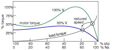
The speed of small squirrel cage induction motors for applications such as driving fans, may be changed by reducing the line voltage. This reduces the torque available to the load which reduces the speed. (Figure below)
motor_starting_ymyoav.png

Variable voltage controls induction motor speed.

OP said:
Why then a fan connected in delta and star connection has a different speed, even though it is the same fan and fed at the same frequency ?
Can speed on an induction motor be controlled by dropping the voltage?
With some loads such as fans, some motors may be speed controlled by dropping the voltage.
Is this done in practice?
For very small fan motors, yes.
For larger motors, eg 1 HP and larger, given the several hundred years of cumulative experience of the responders, myself included, who have not seen this done in practice, probably not. A damper is much cheaper than a star delta starter.
If I was to implement this method of control, I would probably use design "D" motors. The inherent high slip of a design "D" motor may make it the most suitable motor for this control method.
The Cowern Papers give torque/speed curves for various designs of induction motors.
Link
See .pdf page 7
Remember the cube law for fan HP.
At reduced speed the required torque is also reduced.
Will I ever use voltage reduction to control the speed of an integral HP fan?
Probably not.
A damper or stepped control of multiple fans is so much cheaper.
The motor may have to be oversized at full speed use to allow reduced speed use.
Also there would be no danger of a failed motor being replaced with an unsuitable motor.
Is this a good idea? NO
Now let's be friends again.
The first round is on me in Pat's Pub.

Bill
--------------------
"Why not the best?"
Jimmy Carter
 
Bill - the graph you posted is rather useless without the 100%V current vs speed curve. It's easy to show that a reduction in voltage will reduce the torque which causes more slip and a slower operating speed. But, you can't ignore current since it's not a valid operating mode when the corresponding current will be too high. The motor basically has to be designed to have a suitable current vs speed characteristic (the curve is low), which also causes the motor to have a low power factor and poor efficiency. It's why using slip for speed control is generally only seen in packaged fractional HP applications. The motor is specific to the application it's packaged with.
 
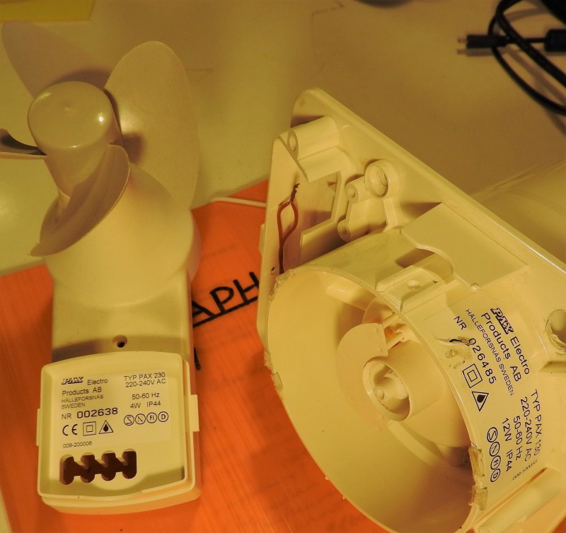
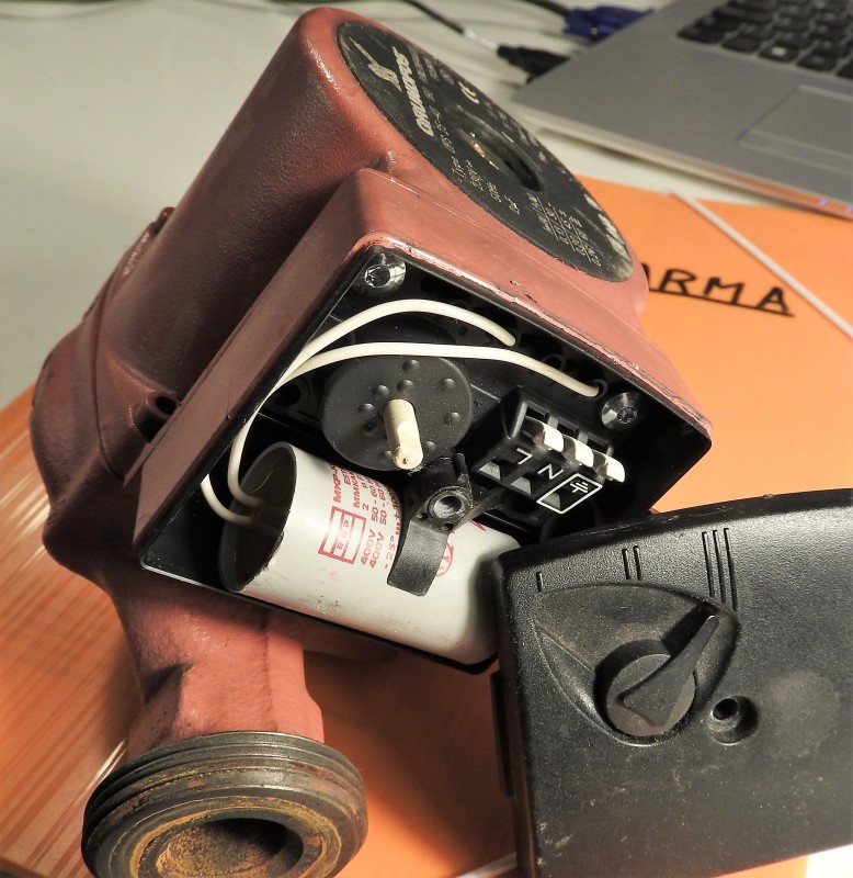
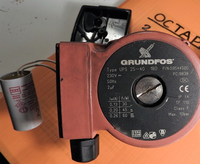
Yes, Bill. SMALL single phase asynchronous motors can - and are - speed controlled by changing the voltage. It has been done for a long time and part of my bread and butter in the eighties and nineties came from designing controllers for such applications. I dug a couple of them out from my garden shed and attach a few pictures. There is also a picture on a circulation pump for heating. All of these motors are very low power and that is what I said in my 19 Feb 17 18:10 answer. The rated Power is from 4 W to 60 W, which is a typical range for this kind of motors.

Zlatko falsely says that ANY asynchronous motor can be controlled that way, which is completely incorrect. I would not even try a 1 HP motor and Zlatko says he can control a 75 HP motor. Which is utterly wrong. To be successful, the rotor resistance needs to be high so that there is a monotone and increasing slip as voltage decreases. Such motors cannot be had and are, hence, not possible to control the way Zlatko says.

Enfas_motor_PAX_1_egcnl9.jpg


Enfas_motor_Grundfos_1_crukmm.jpg


Enfas_motor_Grundfos_2_ezuxnq.jpg


Gunnar Englund
--------------------------------------
Half full - Half empty? I don't mind. It's what in it that counts.
 
Lionel and Gunnar;
Thank you for your patience and your expanded explanations.
Lionel, I had not seen your latest post when I posted. That is the curve set that I was looking for.
May I take advantage of your help with two more questions gentlemen?
1> With the same load, if the motor was upsized to 150%, would that allow the motor to drive the fan at about 55% speed and 100% or less current? I do realize that at this point we will be using a 150 HP motor to drive a load of around 20 HP at the lower speed.
Not very smart but will it work?
2> A premium efficiency motor may be my last choice. I am wondering about the use of a design "D" motor with it's higher slip at higher speeds.
a> Would a design "D" motor work with less than 100% stator current on a star connection?
b> If a design "D" motor will work with acceptable stator current on the star connection, is there a danger of overheating the rotor?
Thank you for your time gentlemen.
Yours
Bill

Bill
--------------------
"Why not the best?"
Jimmy Carter
 
Bill, the rotor losses will be extreme. At 55% and 20 HP output, you will have somewhere like 12 kW rotor losses. Add the very high losses in the stator winding and see the motor go up in smoke.

Gunnar Englund
--------------------------------------
Half full - Half empty? I don't mind. It's what in it that counts.
 
Bill,

#1 - Not star connected. Start with the curves I posted then drop the load curve to 67% (this reduction is the same as upsizing the motor by 1.5 times). The star torque curve will now intersect this new load curve past the breakdown torque peak closer to full speed. So, the speed will only drop around 1-2%. The problem with oversizing and attempting to use a star connection to reduce speed is that the torque is still so high that the motor almost reaches rated speed.

#2a - You might be able to find some motor that would work, but I expect you'll only be capable of proving a case where the speed drops a couple of percentage without overloading the motor.

#2b - I would expect that any time you cause more slip then rated that there is a danger of overheating the rotor. If rated current is going into the motor with significantly less then rated torque coming out, you end up with that extra current heating the rotor instead.

No matter what motor, when connected in star vs the normal delta for running, you can only slide back the curves to the speed where the delta current goes over 175%. Once below that speed, the motor will draw over rated current no matter what load is connected. This is why. In delta when 100% current goes into the motor only 58% of that current flows in each of the delta connected coils. So, the motor is actually only capable of operating at 58% of the rated current continually when connected in star. You simply have to look at 6-lead motor data to see that this current ratio is true - the higher voltage rated star connection will have less current. The ratio of delta to star current is 33% and 58% divided by 33% is 175%. So, the speed where 175% current occurs on the "delta" graph is the lowest speed you could potentially operate at when you attempt to run the motor at the delta voltage, but star connected instead of delta connected.

Overall, I don't really feel like creating a bunch of different scenario graphs trying to prove that something which is never done in practice might just possibly work in theory under one perfect set of circumstances.
 
LinelHutz,
What happens with your Dahlander?
Regarding the both quotes.
I will repeat my post from 8. Mar.
Zlatkodo said:
I am talking about three phase fan that is connected in Delta connection for high speed and Wye connection for low speed, because, that was an initial question.
Also, looking at the picture above ( example of external wiring for this type of connection) , it is clear to everyone (even to beginner), it can not be Dahlander winding.

That means , if this fan is connected to high speed in Delta 400 V then you can connect it to low speed by connection to Wye or keep the Delta connection and decrease the voltage from 400 to 230 V ( line to line). And the Amps will decrease for sure.
And it's clear, you can change the rpm with the same Hz and poles, by changing the slip.

Whether or not this kind of design has a limitation?
Yes, as many others.
Mostly, the limitations are related to rpm range to be regulated.
Any reasonable person would not expect the regulation of rpm from 0 to 100%.
For example the reduction of speed of 2-pole fan motor below the 1500 rpm (at 50 Hz) it is not reasonable too.
Even the high speed of these fans must be designed with slightly higher slip then usual etc....
Regarding the "special" , "standard" , "normal or abnormal" motor , "small or large HP" .
Yes, it is special design as many others. One way to do that is already described:
Zlatkodo said:
This is achieved by adding the turns ( less or more) in each phase winding for middle and low speed, which is equivalent to voltage reducing.
There are other ways too. For example, three speeds of such a fan can be obtained by changing the stator connection from 2Delta to 2Wye and to 1Delta (same number of poles and Hz).
A very similar way is used at triple rated motors, (but for same rpm) in order to increase the efficiency in case of low loads, as well as reconnection from delta to star if the any motor for general application is loaded too low, again in order to increase the efficiency.

Whether or not the rotor is "special"?
Could be, as could be in many other designs.
Regarding the HP.
Is there any particular reason that something valid for "small" three-phase motors is not valid for "large" motors?
What could be a conclusion of all above mentioned?
In some cases of 3phase fan or pump applications, the VFD for speed regulation is not needed at all, if the rpm range is suitable for simple and low cost voltage regulation,
despite the recommendation of some VFD experts.
Skogsgurra
Skogsgurra said:
Zlatko says he can control a 75 HP motor
This claim sounds arrogant and it is not mine. Not my style. Where did you read it?


Zlatko, you say that any size motor can be voltage controlled and, since Lionel chose a 75 HP motor for his example (8 Mar 17 18:36) - and you said that you had nothing to add - I used that size for my example.

I can tell you that you are getting famous in certain quarters. You are the topic of quite a few coffe-break conversations and you are not contributing positively to the good name of Nikola Tesla's countrymen. Please accept practical results and solutions and forget about extrapolating into absurdity. Tesla did and, as you know, he wasn't very successful in his later Days.

Gunnar Englund
--------------------------------------
Half full - Half empty? I don't mind. It's what in it that counts.
 
Your picture of the connections doesn't prove anything about what happens with the motor until you post full details on that motor.

As for the rest. I really have no idea what the actual point of your rambling is except I caught this part - "Is there any particular reason that something valid for "small" three-phase motors is not valid for "large" motors?" It seems this is the conclusion of your ramblings and you're attempting (again) to claim that what works on little specialty motors will work on larger motors. I posted real life data that illustrates why it doesn't work on large motors, not just some random claims that it shouldn't. If you think it does work on large motors then post real life examples of it being used. You have to include ALL data related to the motor and load to do this, not some random picture of who knows what exactly, like that connection diagram.

Also note that voltage control generally won't even work on standard small motors. The motor has to be a special design. The curves of a standard 1/2hp or 1hp squirrel cage induction motor look very similar to the 75hp motor curves and would run into the same issue with the current being too high if you attempted to use slip to run at a lower speed.
 
I answered a question from the initial post.
You disagree and insist that this is a Dahlander winding.
OK.
Thanks to both self-declared experts on all their disqualifications and insults .
It is quite sufficient to evaluate their knowledge.

Regarding the Tesla: unfortunately, only the birth country and similar last name is common to us. Not a knowledge.
I would be very happy if I had at least 10% of his knowledge and ideas.

Tech Support in Winding Design and Motor Repair
 
Circling back to the OP (Hi Paul, I hope you've found this entertaining, at the very least).

I think I can offer two book recommendations that would help the OP with his questions. I have had the same ones answered by these books. One is still in print and one is old and out of print but I still know of no substitute:

Austin Hughes, Electric Motors and Drives

Excellent writing, illustrations very clear, math is essential but limited to only what supports the reader's understanding.

Robert Rosenberg, Electric Motor Repair

Essential techniques in motor repair, built upon solid foundation of how electric motors are made and operated. Covers every sort of electric motor I can think of. The "solid-state" control sections are hopelessly out of date so indulge your inner historian.

Now, something has gone haywire at Amazon and their used book sellers, because the prices are pretty wonky for the Rosenberg book. I bought my used 2nd edition copy 10 years ago for about 40 bucks US and there's no reason for the price to rocket upwards now. It is strangely possible, now that the internet links everything to everything and big data can process associations between such disparate websites as Amazon's used book resellers to a book recommendation on Eng-Tips (which I have done a dozen times since reading Rosenberg's book) and boost the price accordingly, but that my be my personal paranoia. It should still be possible to get a copy of Rosenberg's unique book for 50USD, just maybe not from Amazon bloodsuckers. It is worth looking for.

STF
 
Hello everybody
First I do apologize if my question was unclear so that I generated this discussion.
Just to put things straight my question was referring to electrical motors utilized in fans as for example

Link

(see the ac fans)
If you see AC fans can
- Be connected in delta and wye
- Can work at different tensions (ex 400/3/50 or 400/3/60 or 460/3/60)

in a second hand this enforces the topic for me to increase my knowledge on topic, so, many thanks SparWeb, I will certainly take into consideration these two literature references.
I would like to thank all for having shown me how deep and extended is the subject.
Once more, please accept my excuses if a non-precise question has generated this discussion.
Thanks

 
PaulLag,
thank you for your explanation and the link.
Short conclusion:
- here it is not about Dahlander winding, at all, but about the motor that is connected to Y for low speed and D for high speed.
- Regarding the above-mentioned limitation to single-phase, FPIM (fractional power induction motors): you can find on the link above a list of manufacturer's voltage regulators for 3ph fan motors. Some among them are 40 Amps at 50 Hz (note that is not VFD, but only voltage regulator). It is hard to be a "fractional power home appliance"!!!!

Tech Support for Rewind Shops
 
LOL, have to come back after 2 months to make more claims? The fan motors in the documents found by following the link are all small HP, very high slip and very low efficiency motors specifically designed so they could be speed controlled. There was not a single fan with a high efficiency, low slip motor like you'd find in any standard industrial motor catalog. As for the current ratings of the speed controllers. In this day and age with conservation and high electricity prices being the normal, would you actually want a 10hp or 15hp motor that is only 50% efficient operating in your facility?
 
Status
Not open for further replies.

Part and Inventory Search

Sponsor